Product Description
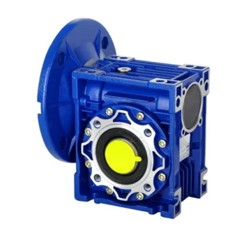
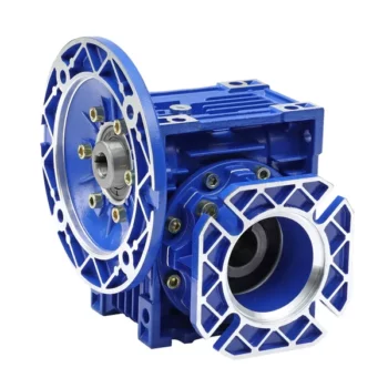
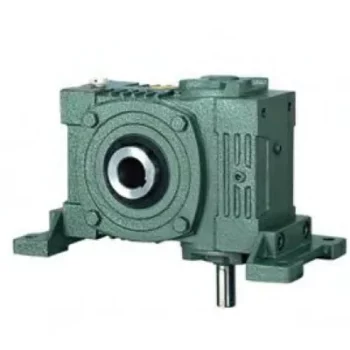
Spiral Bevel Gearbox Box 90 Degree High-Quality Transmission Industrie Right Angle Speed Reducer Alloy Steel Stainless Induction Straight Spiral Bevel Gearboxes
Application of Spiral Bevel Gearbox
Spiral bevel gearboxes are used in a wide variety of applications where it is necessary to transmit power from 1 axis to another at a right angle. Some of the most common applications for spiral bevel gearboxes include:
- Automotive: Spiral bevel gearboxes are used in automotive applications to transmit power from the engine to the wheels. This allows the vehicle to move CHINAMFG and backward.
- Machine tools: Spiral bevel gearboxes are used in machine tools to transmit power from the motor to the cutting tool. This allows the cutting tool to move in a variety of directions, including up and down, left and right, and CHINAMFG and backward.
- Robotics: Spiral bevel gearboxes are used in robotics to transmit power from the motor to the robot arm. This allows the robot arm to move in a variety of directions, including up and down, left and right, and CHINAMFG and backward.
- Wind turbines: Spiral bevel gearboxes are used in wind turbines to transmit power from the rotor to the generator. This allows the generator to generate electricity.
- Conveyor belts: Spiral bevel gearboxes are used in conveyor belts to transmit power from the motor to the conveyor belt. This allows the conveyor belt to move materials from 1 place to another.
Spiral bevel gearboxes are a versatile and reliable component that can be used in a wide variety of applications. They are characterized by their ability to transmit power from 1 axis to another at a right angle, which makes them ideal for applications where space is limited or where the need for compactness is a priority.
Here are some of the advantages and disadvantages of spiral bevel gearboxes:
Advantages:
- Compact size
- High efficiency
- Low noise
- Long life
- Smooth operation
Disadvantages:
- Expensive
- Complex design
- Can be difficult to maintain
Overall, spiral bevel gearboxes are a versatile and reliable component that can be used in a wide variety of applications. They are characterized by their compact size, high efficiency, and low noise. However, they can be expensive and complex to design and maintain.
Here are some additional details about spiral bevel gearboxes:
- Spiral bevel gears are made up of 2 interlocking gears, a pinion and a gear. The pinion is the smaller gear, and the gear is the larger gear. The pinion and the gear have spiral teeth that mesh together.
- Spiral bevel gears are able to transmit power from 1 axis to another at a right angle because of the spiral shape of their teeth. The spiral shape of the teeth allows the gears to mesh smoothly and efficiently.
- Spiral bevel gearboxes are typically made of steel or cast iron. The type of material used to make the gearbox will depend on the application. For example, a gearbox that will be used in a high-torque application will need to be made of a stronger material, such as steel.
- Spiral bevel gearboxes are typically lubricated with oil. The oil helps to reduce friction and wear between the gears.
- Spiral bevel gearboxes can be either open or enclosed. An open gearbox has no cover, while an enclosed gearbox has a cover that protects the gears from dirt and debris.
Spiral bevel gearboxes are a versatile and reliable component that can be used in a wide variety of applications. They are characterized by their compact size, high efficiency, and low noise. However, they can be expensive and complex to design and maintain.
| Application: | Motor, Electric Cars, Motorcycle, Machinery, Marine, Toy, Agricultural Machinery, Car |
|---|---|
| Function: | Distribution Power, Clutch, Change Drive Torque, Change Drive Direction, Speed Changing, Speed Reduction, Speed Increase |
| Layout: | Three-Ring |
| Hardness: | Hardened Tooth Surface |
| Installation: | Torque Arm Type |
| Step: | Stepless |
| Samples: |
US$ 9999/Piece
1 Piece(Min.Order) | |
|---|

How to Install and Align a Worm Reducer Properly
Proper installation and alignment of a worm reducer are crucial for ensuring optimal performance and longevity. Follow these steps to install and align a worm reducer:
- Preparation: Gather all the necessary tools, equipment, and safety gear before starting the installation process.
- Positioning: Place the worm reducer in the desired location, ensuring that it is securely mounted to a stable surface. Use appropriate fasteners and mounting brackets as needed.
- Shaft Alignment: Check the alignment of the input and output shafts. Use precision measurement tools to ensure that the shafts are parallel and in line with each other.
- Base Plate Alignment: Align the base plate of the reducer with the foundation or mounting surface. Ensure that the base plate is level and properly aligned before securing it in place.
- Bolt Tightening: Gradually and evenly tighten the mounting bolts to the manufacturer’s specifications. This helps ensure proper contact between the reducer and the mounting surface.
- Check for Clearance: Verify that there is enough clearance for any rotating components or parts that may move during operation. Avoid any interference that could cause damage or performance issues.
- Lubrication: Apply the recommended lubricant to the worm reducer according to the manufacturer’s guidelines. Proper lubrication is essential for smooth operation and reducing friction.
- Alignment Testing: After installation, run the worm reducer briefly without a load to check for any unusual noises, vibrations, or misalignment issues.
- Load Testing: Gradually introduce the intended load to the worm reducer and monitor its performance. Ensure that the reducer operates smoothly and efficiently under the load conditions.
It’s important to refer to the manufacturer’s installation guidelines and specifications for your specific worm reducer model. Proper installation and alignment will contribute to the gearbox’s reliability, efficiency, and overall functionality.

How to Calculate the Input and Output Speeds of a Worm Gearbox?
Calculating the input and output speeds of a worm gearbox involves understanding the gear ratio and the principles of gear reduction. Here’s how you can calculate these speeds:
- Input Speed: The input speed (N1) is the speed of the driving gear, which is the worm gear in this case. It is usually provided by the manufacturer or can be measured directly.
- Output Speed: The output speed (N2) is the speed of the driven gear, which is the worm wheel. To calculate the output speed, use the formula:
N2 = N1 / (Z1 * i)
Where:
N2 = Output speed (rpm)
N1 = Input speed (rpm)
Z1 = Number of teeth on the worm gear
i = Gear ratio (ratio of the number of teeth on the worm gear to the number of threads on the worm)
It’s important to note that worm gearboxes are designed for gear reduction, which means that the output speed is lower than the input speed. Additionally, the efficiency of the gearbox, friction, and other factors can affect the actual output speed. Calculating the input and output speeds is crucial for understanding the performance and capabilities of the worm gearbox in a specific application.

Advantages of Using a Worm Reducer in Mechanical Systems
Worm reducers offer several advantages that make them suitable for various mechanical systems:
- High Gear Reduction Ratio: Worm gearboxes provide significant speed reduction, making them ideal for applications that require a high gear reduction ratio without the need for multiple gears.
- Compact Design: Worm reducers have a compact and space-saving design, allowing them to be used in applications with limited space.
- Self-Locking: Worm gearboxes exhibit self-locking properties, which means that the worm screw can prevent the worm wheel from reversing its motion. This is beneficial for applications where the gearbox needs to hold a load in place without external braking mechanisms.
- Smooth and Quiet Operation: Worm gearboxes operate with a sliding motion between the teeth, resulting in smoother and quieter operation compared to some other types of gearboxes.
- High Torque Transmission: Worm gearboxes can transmit high torque levels, making them suitable for applications that require powerful torque output.
- Heat Dissipation: The sliding action between the worm screw and the worm wheel contributes to heat dissipation, which can be advantageous in applications that generate heat during operation.
- Stable Performance: Worm reducers offer stable and reliable performance, making them suitable for continuous operation in various industrial and mechanical systems.
Despite these advantages, it’s important to note that worm gearboxes also have limitations, such as lower efficiency compared to other gear types due to the sliding motion and potential for higher heat generation. Therefore, selecting the appropriate type of gearbox depends on the specific requirements and constraints of the application.


editor by CX 2023-09-23