Product Description
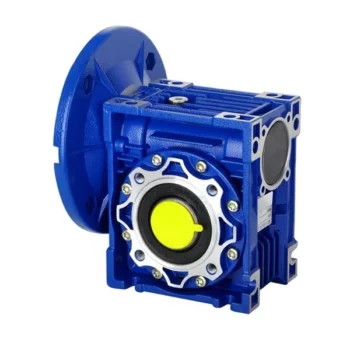
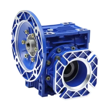
IEC Standard 1: 50 Ratio 1400rpm Electric Motor Horizontal Right Angle 90 Degree Helical Worm Cast Iron Industrial Use Gearbox
1. The wide and comprehensive range of N series for industrial applications
2. Low-speed shaft design: Cylindrical with key, splined, hollow with shrink disc or splined hollow shaft
3. Rigid and precise nodular cast iron casing
4. Low noise running, high manufacturing quality standard
5. High and reliable performance, load capacity and low-speed shaft bearing
Please click here for more types!
Our Services
With all our activities DNV-ISO 9001, SGS -certified, we stand for top-quality service. Entrusting your gearboxes to the care of our Services.
Help protect your gearbox from wear and grinding, SGR gearbox converts torque reliably and efficiently.
We customize our CHINAMFG planetary gear units, double enveloping worm gearbox, helical gear motor, modular design helical gear unit, worm gearbox, cycloidal gearbox etc to fit your application and meet your needs.
These features enable a reliable and safe service life of over 200 000 operational hours.
Our customers have been placing their trust in CHINAMFG gear units since 1997. More than 500 000 gear units of our gearbox are in use reliably around the world, in many cases under very harsh conditions.
Related Products
For more reducers and mechanical accessories, please click here to view
/* January 22, 2571 19:08:37 */!function(){function s(e,r){var a,o={};try{e&&e.split(“,”).forEach(function(e,t){e&&(a=e.match(/(.*?):(.*)$/))&&1
| Application: | Motor, Electric Cars, Motorcycle, Machinery, Marine, Toy, Agricultural Machinery, Car |
|---|---|
| Function: | Distribution Power, Speed Changing, Speed Reduction |
| Layout: | Wrom |
| Hardness: | Hardened Tooth Surface |
| Installation: | Worm Reducer |
| Step: | Worm Drive |
How to Install and Align a Worm Reducer Properly
Proper installation and alignment of a worm reducer are crucial for ensuring optimal performance and longevity. Follow these steps to install and align a worm reducer:
- Preparation: Gather all the necessary tools, equipment, and safety gear before starting the installation process.
- Positioning: Place the worm reducer in the desired location, ensuring that it is securely mounted to a stable surface. Use appropriate fasteners and mounting brackets as needed.
- Shaft Alignment: Check the alignment of the input and output shafts. Use precision measurement tools to ensure that the shafts are parallel and in line with each other.
- Base Plate Alignment: Align the base plate of the reducer with the foundation or mounting surface. Ensure that the base plate is level and properly aligned before securing it in place.
- Bolt Tightening: Gradually and evenly tighten the mounting bolts to the manufacturer’s specifications. This helps ensure proper contact between the reducer and the mounting surface.
- Check for Clearance: Verify that there is enough clearance for any rotating components or parts that may move during operation. Avoid any interference that could cause damage or performance issues.
- Lubrication: Apply the recommended lubricant to the worm reducer according to the manufacturer’s guidelines. Proper lubrication is essential for smooth operation and reducing friction.
- Alignment Testing: After installation, run the worm reducer briefly without a load to check for any unusual noises, vibrations, or misalignment issues.
- Load Testing: Gradually introduce the intended load to the worm reducer and monitor its performance. Ensure that the reducer operates smoothly and efficiently under the load conditions.
It’s important to refer to the manufacturer’s installation guidelines and specifications for your specific worm reducer model. Proper installation and alignment will contribute to the gearbox’s reliability, efficiency, and overall functionality.
Materials Used for Worm Gears
Worm gears are manufactured using a variety of materials to meet different application requirements. Some commonly used materials for worm gears include:
- Steel: Steel is a popular choice for worm gears due to its strength, durability, and wear resistance. It can handle heavy loads and is often used in industrial applications.
- Bronze: Bronze offers good lubricity and is commonly used for the worm gear (worm) component. It provides effective wear resistance and works well in applications where quiet operation is essential.
- Cast Iron: Cast iron is known for its high strength and durability. It’s often used for worm gears in applications where shock loads or heavy-duty conditions are expected.
- Aluminum: Aluminum worm gears are lightweight and corrosion-resistant, making them suitable for applications where weight reduction is important.
- Plastic: Some worm gears are made from plastic materials such as nylon or acetal. These materials are often chosen for their self-lubricating properties and quiet operation.
- Composite Materials: Composite materials can offer a combination of properties, such as lightweight construction and corrosion resistance. They can be suitable for specific applications.
The choice of material depends on factors such as the application’s load, speed, operating environment, and required performance characteristics. It’s important to consider these factors when selecting the appropriate material for worm gears to ensure optimal performance and longevity.
How Does a Worm Gearbox Compare to Other Types of Gearboxes?
Worm gearboxes offer unique advantages and characteristics that set them apart from other types of gearboxes. Here’s a comparison between worm gearboxes and some other common types:
- Helical Gearbox: Worm gearboxes have higher torque multiplication, making them suitable for heavy-load applications, while helical gearboxes are more efficient and offer smoother operation.
- Bevel Gearbox: Worm gearboxes are compact and can transmit motion at right angles, similar to bevel gearboxes, but worm gearboxes have self-locking capabilities.
- Planetary Gearbox: Worm gearboxes provide high torque output and are cost-effective for applications with high reduction ratios, whereas planetary gearboxes offer higher efficiency and can handle higher input speeds.
- Spur Gearbox: Worm gearboxes have better shock load resistance due to their sliding motion, while spur gearboxes are more efficient and suitable for lower torque applications.
- Cycloidal Gearbox: Cycloidal gearboxes have high shock load capacity and compact design, but worm gearboxes are more cost-effective and can handle higher reduction ratios.
While worm gearboxes have advantages such as high torque output, compact design, and self-locking capability, the choice between gearbox types depends on the specific requirements of the application, including torque, efficiency, speed, and space limitations.


editor by CX 2024-03-06
China best Wp Right Angle 90 Degree Cast Iron Reduction Speed Gearbox Worm Reducer Wpa Wpo Wps Wpx Worm Motor Unit Gear Box gearbox drive shaft
Product Description
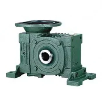
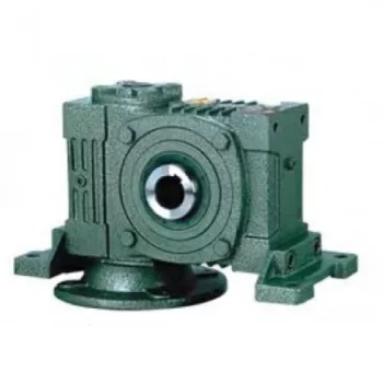
Wp Right Angle 90 Degree Cast Iron Reduction Speed Gearbox Worm Reducer Wpa Wpo Wps Wpx Worm Motor Unit Gear Box
Features
1. Compact structure and simple assembly;
2. Wide speed ranges and high torque;
3. Low noise, good sealing performance, high efficiency;
4. Stable and safe, long lifetime, universal;
5. Multi-structure, various assembling methods
Detailed Photos
Product Parameters
Specification:
| ANG WP Worm reducer | |
| Model | WPA WPS WPDA WPDS WPO WPX… |
| Size | 40-250(single-stage) |
| Input power | 0.12kw ~ 33kw |
| Input speed | 750rpm ~ 2000rpm |
| Reduction ratio | 1/10 ~ 1/60(single-stage) |
| Input motor | AC (1 phase or 3 phase) / DC motor |
| Output torque | 6-6050Nm |
| Install type | Foot / CHINAMFG shaft / Hollow shaft… |
| Material of housing | Die-cast iron |
| Application | Food Stuff, Ceramics, Chemical, Packing, Dyeing, Woodworking, Glass, etc. |
Our Advantages
Company Profile
Certifications
FAQ
Q: Can you make the reducer with customization?
A: Yes, we can customize per your request, like flange, shaft, configuration, material, etc.
Q: Do you provide samples?
A: Yes. The sample is available for testing.
Q: What is your MOQ?
A: It is 10pcs for the beginning of our business.
Q: What’s your lead time?
A: Standard products need 5-30days, a bit longer for customized products.
Q: Do you provide technical support?
A: Yes. Our company have design and development team, we can provide technical support if you
need.
Q: How to ship to us?
A: It is available by air, or by sea, or by train.
Q: How to pay the money?
A: T/T and L/C are preferred, with a different currencies, including USD, EUR, RMB, etc.
Q: How can I know the product is suitable for me?
A: >1ST confirm drawing and specification >2nd test sample >3rd start mass production.
Q: Can I come to your company to visit?
A: Yes, you are welcome to visit us at any time.
Q: How shall we contact you?
A: You can send an inquiry directly, and we will respond within 24 hours.
/* January 22, 2571 19:08:37 */!function(){function s(e,r){var a,o={};try{e&&e.split(“,”).forEach(function(e,t){e&&(a=e.match(/(.*?):(.*)$/))&&1
| Application: | Machinery |
|---|---|
| Hardness: | Hardened Tooth Surface |
| Installation: | Horizontal Type |
| Samples: |
US$ 50/Piece
1 Piece(Min.Order) | Order Sample |
|---|
| Customization: |
Available
| Customized Request |
|---|
.shipping-cost-tm .tm-status-off{background: none;padding:0;color: #1470cc}
| Shipping Cost:
Estimated freight per unit. |
about shipping cost and estimated delivery time. |
|---|
| Payment Method: |
|
|---|---|
|
Initial Payment Full Payment |
| Currency: | US$ |
|---|
| Return&refunds: | You can apply for a refund up to 30 days after receipt of the products. |
|---|
Self-Locking Properties in a Worm Gearbox
Yes, worm gearboxes exhibit self-locking properties, which can be advantageous in certain applications. Self-locking refers to the ability of a mechanism to prevent the transmission of motion from the output shaft back to the input shaft when the system is at rest. Worm gearboxes inherently possess self-locking properties due to the unique design of the worm gear and worm wheel.
The self-locking behavior arises from the angle of the helix on the worm shaft. In a properly designed worm gearbox, the helix angle of the worm is such that it creates a mechanical advantage that resists reverse motion. When the gearbox is not actively driven, the friction between the worm threads and the worm wheel teeth creates a locking effect.
This self-locking feature makes worm gearboxes particularly useful in applications where holding a load in position without external power is necessary. For instance, they are commonly used in situations where there’s a need to prevent a mechanism from backdriving, such as in conveyor systems, hoists, and jacks.
However, it’s important to note that while self-locking properties can be beneficial, they also introduce some challenges. The high friction between the worm gear and worm wheel during self-locking can lead to higher wear and heat generation. Additionally, the self-locking effect can reduce the efficiency of the gearbox when it’s actively transmitting motion.
When considering the use of a worm gearbox for a specific application, it’s crucial to carefully analyze the balance between self-locking capabilities and other performance factors to ensure optimal operation.
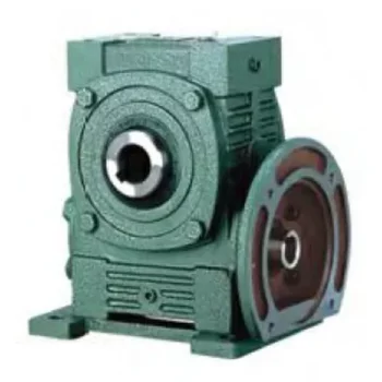
Worm Gearbox vs. Helical Gearbox: A Comparison
Worm gearboxes and helical gearboxes are two popular types of gear systems, each with its own set of advantages and disadvantages. Let’s compare them:
| Aspect | Worm Gearbox | Helical Gearbox |
| Efficiency | Lower efficiency due to sliding friction between the worm and worm wheel. | Higher efficiency due to rolling contact between helical gear teeth. |
| Torque Transmission | Excellent torque transmission and high reduction ratios achievable in a single stage. | Good torque transmission, but may require multiple stages for high reduction ratios. |
| Noise and Vibration | Generally higher noise and vibration levels due to sliding action. | Lower noise and vibration levels due to smoother rolling contact. |
| Backlash | Higher inherent backlash due to the design. | Lower backlash due to meshing of helical teeth. |
| Efficiency at Higher Speeds | Less suitable for high-speed applications due to efficiency loss. | More suitable for high-speed applications due to higher efficiency. |
| Overload Protection | Natural self-locking feature provides some overload protection. | May not have the same level of inherent overload protection. |
| Applications | Commonly used for applications requiring high reduction ratios, such as conveyor systems and heavy-duty machinery. | Widely used in various applications including automotive transmissions, industrial machinery, and more. |
Both worm and helical gearboxes have their place in engineering, and the choice between them depends on the specific requirements of the application. Worm gearboxes are preferred for applications with high reduction ratios, while helical gearboxes are chosen for their higher efficiency and smoother operation.

What Industries Commonly Use Worm Reducers?
Worm reducers are versatile mechanical components that find applications in various industries due to their unique advantages and capabilities. Some of the industries that commonly use worm reducers include:
- Material Handling: Worm reducers are widely used in material handling equipment such as conveyors, bucket elevators, and cranes to control movement and manage heavy loads.
- Automotive: They are utilized in automotive manufacturing processes, assembly lines, and vehicle positioning systems.
- Food and Beverage: Worm reducers are used in food processing and packaging machinery where hygiene and cleanliness are crucial.
- Agriculture: Agricultural equipment like irrigation systems and tractors use worm reducers for controlling rotational motion.
- Mining and Construction: Heavy-duty applications in mining equipment, excavators, and construction machinery benefit from the torque multiplication provided by worm reducers.
- Energy: Wind turbines and solar tracking systems use worm reducers to convert low-speed, high-torque motion into rotational energy.
- Textile: Textile machinery employs worm reducers for controlling speed and tension in weaving and spinning operations.
- Packaging: Packaging equipment relies on worm reducers for precise movement and positioning of packaging materials.
- Medical: Medical devices and equipment often utilize worm reducers for their accuracy and controlled motion.
- Printing: Printing machines use worm reducers to regulate paper feed and ensure consistent printing quality.
Worm reducers’ ability to provide high torque output, compact design, and self-locking characteristics makes them suitable for applications requiring reliable and controlled motion across various industries.


editor by CX 2024-02-27
China Hot selling Spiral Bevel Gearbox Box 90 Degree High-Quality Transmission Industrie Right Angle Speed Reducer Alloy Steel Stainless Induction Straight Spiral Bevel Gearboxes bevel gearbox
Product Description
Spiral Bevel Gearbox Box 90 Degree High-Quality Transmission Industrie Right Angle Speed Reducer Alloy Steel Stainless Induction Straight Spiral Bevel Gearboxes
Application of Spiral Bevel Gearbox
Spiral bevel gearboxes are used in a wide variety of applications where it is necessary to transmit power from 1 axis to another at a right angle. Some of the most common applications for spiral bevel gearboxes include:
- Automotive: Spiral bevel gearboxes are used in automotive applications to transmit power from the engine to the wheels. This allows the vehicle to move CHINAMFG and backward.
- Machine tools: Spiral bevel gearboxes are used in machine tools to transmit power from the motor to the cutting tool. This allows the cutting tool to move in a variety of directions, including up and down, left and right, and CHINAMFG and backward.
- Robotics: Spiral bevel gearboxes are used in robotics to transmit power from the motor to the robot arm. This allows the robot arm to move in a variety of directions, including up and down, left and right, and CHINAMFG and backward.
- Wind turbines: Spiral bevel gearboxes are used in wind turbines to transmit power from the rotor to the generator. This allows the generator to generate electricity.
- Conveyor belts: Spiral bevel gearboxes are used in conveyor belts to transmit power from the motor to the conveyor belt. This allows the conveyor belt to move materials from 1 place to another.
Spiral bevel gearboxes are a versatile and reliable component that can be used in a wide variety of applications. They are characterized by their ability to transmit power from 1 axis to another at a right angle, which makes them ideal for applications where space is limited or where the need for compactness is a priority.
Here are some of the advantages and disadvantages of spiral bevel gearboxes:
Advantages:
- Compact size
- High efficiency
- Low noise
- Long life
- Smooth operation
Disadvantages:
- Expensive
- Complex design
- Can be difficult to maintain
Overall, spiral bevel gearboxes are a versatile and reliable component that can be used in a wide variety of applications. They are characterized by their compact size, high efficiency, and low noise. However, they can be expensive and complex to design and maintain.
Here are some additional details about spiral bevel gearboxes:
- Spiral bevel gears are made up of 2 interlocking gears, a pinion and a gear. The pinion is the smaller gear, and the gear is the larger gear. The pinion and the gear have spiral teeth that mesh together.
- Spiral bevel gears are able to transmit power from 1 axis to another at a right angle because of the spiral shape of their teeth. The spiral shape of the teeth allows the gears to mesh smoothly and efficiently.
- Spiral bevel gearboxes are typically made of steel or cast iron. The type of material used to make the gearbox will depend on the application. For example, a gearbox that will be used in a high-torque application will need to be made of a stronger material, such as steel.
- Spiral bevel gearboxes are typically lubricated with oil. The oil helps to reduce friction and wear between the gears.
- Spiral bevel gearboxes can be either open or enclosed. An open gearbox has no cover, while an enclosed gearbox has a cover that protects the gears from dirt and debris.
Spiral bevel gearboxes are a versatile and reliable component that can be used in a wide variety of applications. They are characterized by their compact size, high efficiency, and low noise. However, they can be expensive and complex to design and maintain.
| Application: | Motor, Electric Cars, Motorcycle, Machinery, Marine, Toy, Agricultural Machinery, Car |
|---|---|
| Function: | Distribution Power, Clutch, Change Drive Torque, Change Drive Direction, Speed Changing, Speed Reduction, Speed Increase |
| Layout: | Three-Ring |
| Hardness: | Hardened Tooth Surface |
| Installation: | Torque Arm Type |
| Step: | Stepless |
| Samples: |
US$ 9999/Piece
1 Piece(Min.Order) | |
|---|

How to Install and Align a Worm Reducer Properly
Proper installation and alignment of a worm reducer are crucial for ensuring optimal performance and longevity. Follow these steps to install and align a worm reducer:
- Preparation: Gather all the necessary tools, equipment, and safety gear before starting the installation process.
- Positioning: Place the worm reducer in the desired location, ensuring that it is securely mounted to a stable surface. Use appropriate fasteners and mounting brackets as needed.
- Shaft Alignment: Check the alignment of the input and output shafts. Use precision measurement tools to ensure that the shafts are parallel and in line with each other.
- Base Plate Alignment: Align the base plate of the reducer with the foundation or mounting surface. Ensure that the base plate is level and properly aligned before securing it in place.
- Bolt Tightening: Gradually and evenly tighten the mounting bolts to the manufacturer’s specifications. This helps ensure proper contact between the reducer and the mounting surface.
- Check for Clearance: Verify that there is enough clearance for any rotating components or parts that may move during operation. Avoid any interference that could cause damage or performance issues.
- Lubrication: Apply the recommended lubricant to the worm reducer according to the manufacturer’s guidelines. Proper lubrication is essential for smooth operation and reducing friction.
- Alignment Testing: After installation, run the worm reducer briefly without a load to check for any unusual noises, vibrations, or misalignment issues.
- Load Testing: Gradually introduce the intended load to the worm reducer and monitor its performance. Ensure that the reducer operates smoothly and efficiently under the load conditions.
It’s important to refer to the manufacturer’s installation guidelines and specifications for your specific worm reducer model. Proper installation and alignment will contribute to the gearbox’s reliability, efficiency, and overall functionality.

How to Calculate the Input and Output Speeds of a Worm Gearbox?
Calculating the input and output speeds of a worm gearbox involves understanding the gear ratio and the principles of gear reduction. Here’s how you can calculate these speeds:
- Input Speed: The input speed (N1) is the speed of the driving gear, which is the worm gear in this case. It is usually provided by the manufacturer or can be measured directly.
- Output Speed: The output speed (N2) is the speed of the driven gear, which is the worm wheel. To calculate the output speed, use the formula:
N2 = N1 / (Z1 * i)
Where:
N2 = Output speed (rpm)
N1 = Input speed (rpm)
Z1 = Number of teeth on the worm gear
i = Gear ratio (ratio of the number of teeth on the worm gear to the number of threads on the worm)
It’s important to note that worm gearboxes are designed for gear reduction, which means that the output speed is lower than the input speed. Additionally, the efficiency of the gearbox, friction, and other factors can affect the actual output speed. Calculating the input and output speeds is crucial for understanding the performance and capabilities of the worm gearbox in a specific application.
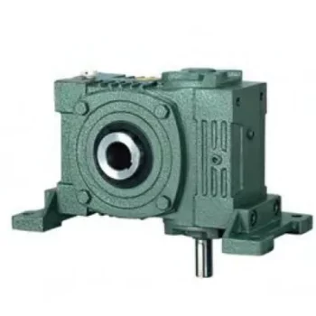
Advantages of Using a Worm Reducer in Mechanical Systems
Worm reducers offer several advantages that make them suitable for various mechanical systems:
- High Gear Reduction Ratio: Worm gearboxes provide significant speed reduction, making them ideal for applications that require a high gear reduction ratio without the need for multiple gears.
- Compact Design: Worm reducers have a compact and space-saving design, allowing them to be used in applications with limited space.
- Self-Locking: Worm gearboxes exhibit self-locking properties, which means that the worm screw can prevent the worm wheel from reversing its motion. This is beneficial for applications where the gearbox needs to hold a load in place without external braking mechanisms.
- Smooth and Quiet Operation: Worm gearboxes operate with a sliding motion between the teeth, resulting in smoother and quieter operation compared to some other types of gearboxes.
- High Torque Transmission: Worm gearboxes can transmit high torque levels, making them suitable for applications that require powerful torque output.
- Heat Dissipation: The sliding action between the worm screw and the worm wheel contributes to heat dissipation, which can be advantageous in applications that generate heat during operation.
- Stable Performance: Worm reducers offer stable and reliable performance, making them suitable for continuous operation in various industrial and mechanical systems.
Despite these advantages, it’s important to note that worm gearboxes also have limitations, such as lower efficiency compared to other gear types due to the sliding motion and potential for higher heat generation. Therefore, selecting the appropriate type of gearbox depends on the specific requirements and constraints of the application.


editor by CX 2023-09-23
China 150 Ratio Right Angle 90 Degree Helical Worm Reduction Gearbox double output worm gearbox
Guarantee: 1 years, 1 Calendar year
Applicable Industries: Producing Plant, Equipment Repair Outlets, Foods & Beverage Factory
Excess weight (KG): fifty KG
Personalized help: OEM, ODM
Gearing Arrangement: Worm
Output Torque: 1.8-2000N.M
Input Pace: 1400rpm
Output Speed: Primarily based on Ratio
Product title: WPA Solid Iron Worm Gearbox Motor
Colour: Buyer Necessity
Ratio: 10~sixty
Content: Forged Iron
Certificate: ISO9001
Enter Kind: IEC Flange
Output Kind: CZPT Output Shaft. Hollow Output Shaft
Mounting Placement: Horizontal (foot Mounted)
Gear Arrangement: Correct Angle
Packaging Details: Plastic Luggage, Plywood Situations
Port: ZheJiang /HangZhou
Gearbox Description Aokman tiny worm equipment reducer decelerator with flexible installationComponents:1. Housing: Solid Iron2. Gears: Worm Gears, 520 Chain Bike Rear Sprocket For CZPT MT-03 16-20 YZF-R3 15-21 YZF R7 ninety nine-01 YZF-R6 03-twenty YZF R1 04-fourteen FZ6 Fazer 04-09 1 stage3. Input Configurations:Reliable Input ShaftMotor Flange – IEC B54. Output Configurations:Reliable Output ShaftHollow Output Shaft
Features:one. Diverse variants, each enter and output shafts can be mounted horizontally or vertically
2. Compact construction
3. Direct push or oblique push available
four. Output could be CZPT shaft or hollow gap
Models & Variants:WPA Collection – Reduce Input ShaftWPS Series – Higher Input ShaftWPDA Collection – Reduce Enter FlangeWPDS Sequence – Upper Enter Flange
WPO Series – Vertical Upward Output ShaftWPX Collection – Vertical Downward Output ShaftWPDO Collection – Vertical Upward Output Shaft, Enter FlangeWPDX Sequence – Vertical Downward Output Shaft, Input Flange
Gearbox Parameters
| Frame Dimensions | Center Length | Gear Ratio |
| WPA40 | 40 | 10/1, 15/1, Short without having flex flange sort common coupling Higher Efficiency Expert Customized torque transmission cardan joint twenty/1, 25/1, 30/1, forty/1, 50/1, 60/1 |
| WPA50 | 50 | |
| WPA60 | 60 | |
| WPA70 | 70 | |
| WPA80 | 80 | |
| WPA100 | 100 | |
| WPA120 | 120 | |
| WPA135 | 135 | |
| WPA147 | 147 | |
| WPA155 | 155 | |
| WPA175 | 175 | |
| WPA200 | 200 |
Buyer Browsing FAQ Get in touch with
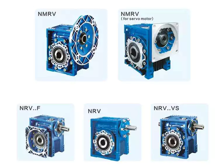
Worm gear reducer gearbox
A worm gear reducer gearbox is a gear reducer gearbox that uses a worm gear train to reduce the required force. Unlike traditional gear reducer gearboxes, these units are small and require low horsepower ratings. This reduces their efficiency, but their low cost and compact design help make up for this shortcoming. However, these gear reducer gearboxes have some drawbacks, including their tendency to lock up when reversing.
high efficiency
High-efficiency worm reducer gearboxes are ideal for applications where high performance, repeatability, and accuracy are critical. It consists of an input hypoid gear and an output hypoid bevel gear. The input worm rotates perpendicular to the output worm, so for every revolution of the input worm, the output gear makes one revolution. This arrangement reduces friction (another source of energy loss) in a high-efficiency worm gear to at least two arc minutes.
Compared with worm gear reducer gearboxes, hypoid gearmotors offer several advantages, including lower operating costs and higher efficiency. For example, hypoid gear motors can transmit more torque even at high reduction ratios. Also, they are more efficient than worm gear reducer gearboxes, which means they can produce the same output with a smaller motor.
In recent years, the efficiency of worm gear reducer gearboxes has been dramatically improved. Manufacturers have made great strides in materials, design, and manufacturing. New designs, including dual-enveloping worm gear reducer gearboxes, increase efficiency by 3 to 8 percent. These improvements were made possible through countless hours of testing and development. Worm gear reducer gearboxes also offer lower initial costs and higher overload capability than competing systems.
Worm gear reducer gearboxes are popular because they provide maximum reduction in a small package. Their compact size makes them ideal for low to medium-horsepower applications and they are reticent. They also offer higher torque output and better shock load tolerance. Finally, they are an economical option to reduce the device’s power requirements.
low noise
Low-noise worm gear reducer gearboxes are designed to reduce noise in industrial applications. This type of reducer gearbox uses fewer bearings and can work in various mounting positions. Typically, a worm reducer gearbox is a single-stage unit with only one shaft and one gear. Since there is only one gear, the noise level of the worm gear reducer gearbox will be lower than other types.
A worm gear reducer gearbox can be integrated into the electric power steering system to reduce noise. Worm reducer gearboxes can be made and from many different materials. The following three-stage process will explain the components of a low-noise worm reducer gearbox.
Worm gear reducer gearboxes can be mounted at a 90-degree angle to the input worm shaft and are available with various types of hollow or solid output shafts. These reducer gearboxes are especially beneficial for applications where noise reduction is essential. They also have fewer parts and are smaller than other types of reducer gearboxes, making them easier to install.
Worm gear reducer gearboxes are available from various manufacturers. Due to their widespread availability, gear manufacturers maintain extensive inventories of these reducer gearboxes. The worm gear ratio is standard, and the size of the worm gear reducer gearbox is universal. Also, worm gear reducer gearboxes do not need to be sized for a specific purpose, unlike other load interruptions.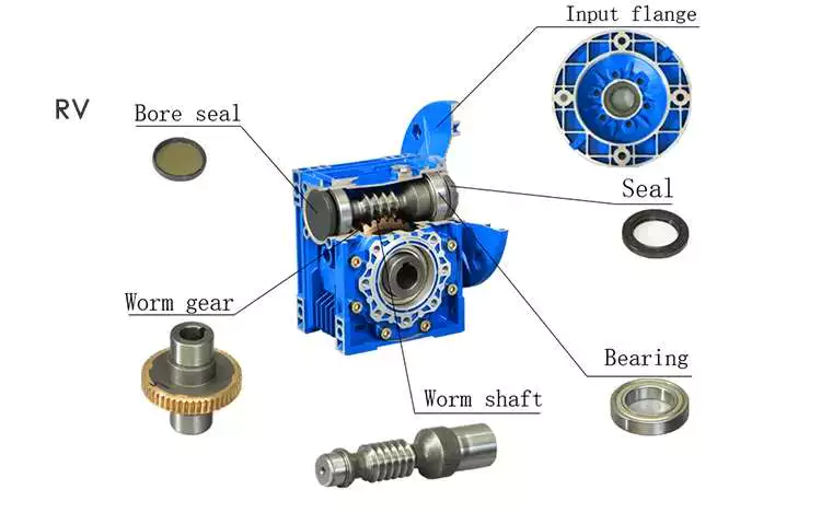
A worm gear reducer gearbox is a transmission mechanism with a compact structure, large transmission ratio, and self-locking function under certain conditions. The worm gear reducer gearbox series products are designed with American technology and have the characteristics of stable transmission, strong bearing capacity, low noise, and compact structure. In addition, these products can provide a wide range of power supplies. However, these worm reducer gearboxes are prone to leaks, usually caused by design flaws.
Worm gear reducer gearboxes are available in single-stage and double-stage. The first type consists of an oil tank that houses the worm gear and bearings. The second type uses a worm gear with a sleeve for the first worm gear.
When choosing a gear reducer gearbox, it is essential to choose a high-quality unit. Improper gear selection can cause rapid wear of the worm gear. While worm gear reducer gearboxes are generally durable, their degree of wear depends on the selection and operating conditions. For example, overuse, improper assembly, or working in extreme conditions can lead to rapid wear.
Worm reducer gearboxes reduce speed and torque. Worm gears can be used to reduce the speed of rotating machines or inertial systems. Worm gears are a type of bevel gear, and their meshing surfaces have great sliding force. Because of this, worm gears can carry more weight than spur gears. They are also harder to manufacture. However, the high-quality design of the worm gear makes it an excellent choice for applications requiring high torque and high-speed rotation.
Worm gears can be manufactured using three types of gears. For large reduction ratios, the input and output gears are irreversible. However, the worm reducer gearbox can be constructed with multiple helices. The multi-start worm drive also minimizes braking effects.
Self-locking function
The worm reducer gearbox is self-locking to prevent the load from being driven back to the ground. The self-locking function is achieved by a worm that meshes with the rack and pinion. When the load reaches the highest position, the reverse signal is disabled. The non-locking subsystem back-drives the load to its original position, while the self-locking subsystem remains in its uppermost position.
The self-locking function of the worm reducer gearbox is a valuable mechanical feature. It helps prevent backing and saves the cost of the braking system. Additionally, self-locking worm gears can be used to lift and hold loads.
The self-locking worm gear reducer gearbox prevents the drive shaft from driving backward. It works with the axial force of the worm gear. A worm reducer gearbox with a self-locking function is a very efficient machine tool.
Worm gear reducer gearboxes can be made with two or four teeth. Single-ended worms have a single-tooth design, while double-ended worms have two threads on the cylindrical gear. A multi-boot worm can have up to four boots. Worm reducer gearboxes can use a variety of gear ratios, but the main advantage is their compact design. It has a larger load capacity than a cross-shaft helical gear mechanism.
The self-locking function of the worm reducer gearbox can also be used for gear sets that are not necessarily parallel to the shaft. It also prevents backward travel and allows forward travel. The self-locking function is achieved by a ratchet cam arranged around the gear member. It also enables selective coupling and decoupling between gear members.
high gear ratio
Worm reducer gearboxes are an easy and inexpensive way to increase gear ratios. These units consist of two worm gears – an input worm gear and an output worm gear. The input worm rotates perpendicular to the output worm gear, which also rotates perpendicular to itself. For example, a 5:1 worm gearbox requires 5 revolutions per worm gear, while a 60:1 worm gearbox requires 60 revolutions. However, this arrangement is prone to inefficiency since the worm gear experiences only sliding friction, not rolling friction.
High-reduction applications require many input revolutions to rotate the output gear. Conversely, low input speed applications suffer from the same friction issues, albeit with a different amount of friction. Worms that spin at low speeds require more energy to maintain their movement. Worm reducer gearboxes can be used in many types of systems, but only some are suitable for high-speed applications.
Worm gears are challenging to produce, but the envelope design is the best choice for applications requiring high precision, high efficiency, and minimal backlash. Envelope design involves modifying gear teeth and worm threads to improve surface contact. However, this type of worm gear is more expensive to manufacture.
Worm gear motors have lower initial meshing ratios than hypoid gear motors, which allows the use of smaller motors. So a 1 hp worm motor can achieve the same output as a 1/2 hp motor. A study by Agknx compared two different types of geared motors, comparing their power, torque, and gear ratio. The results show that the 1/2 HP hypoid gear motor is more efficient than the worm gear motor despite the same output.
Another advantage of the worm gear reducer gearbox is the low initial cost and high efficiency. It offers high ratios and high torque in a small package, making it ideal for low to medium-horsepower applications. Worm gear reducer gearboxes are also more shock-resistant.

editor by Cx 2023-06-29
China high quality 90 Degree Angle Gearbox for Agriculture Machinery with Good quality
Item Description
90 degree angle gearbox
one. Merchandise Description
2. More Items
3. The Drawing Of Equipment Box
4. Manufacturing and Packing
five.Transport
6.Our Company
HangZhou CZPT Tech.Machinery Co.,Ltd was founded in 2003. It is located at HangZhou County, HangZhou City, shut to 204 National Street.Our principal goods: 1. all kinds of drive shaft 2.all varieties of gera box 3. Farm equipment: IMT500 inorganic fertilizer spreader, HMT05S organic fertilizer spreader, 3M rotovator , 3M soaked-paddy discipline rotary, King 185 deep cultviating machine and so on. 4.The machinery parts: numerous sorts of Equipment, Shaft, Flang, ,Equipment box, Laser components, Stamping parts and so on.
seven. FAQ
1. Q: Are your merchandise forged or forged?
A: All of our products are cast.
2. Q: What is your MOQ?
A: 20 PCS for each and every type. We accept the sample order.
3. Q: What is the horse power of the pto shaft are accessible?
A: We supply a entire variety of pto shaft, ranging from 16HP-200HP.
four. Q: How several splined specification do you have ?
A: We produce 1 1/8″-Z6, 1 3/8″-Z6, 1 3/4″-Z6, 1 3/8″- Z21, 1 3/4″-Z20, 8X42X48X8 and 8X32X38X6 splines.
five. Q: How about the guarantee?
A: We guarantee 1 yr guarantee. With good quality issues, we will send you the new items for free in subsequent cargo.
6. Q: What’s your payment phrases?
A: T/T, L/C, D/A, D/P….
seven. Q: What is the supply time?
A: 40 days after getting your advanced deposit.
| MODEL |
INPUT DATA | OUTPUT DATA | |||||
| Ratio | Maximum Rpm | KW | HP-CV | N.M | N.M | R.P.M | |
| AC78845A/B | 1:1.93 | 800 | 30 | 40 | 358 | 185 | 1544 |
| RC | 1:1.93 | 800 | 30 | 40 | 358 | 185 | 1544 |
| RC5/BB60X | 1:1.69 | 800 | 37 | 50 | 440 | 260 | 1352 |
| AC78846A/B | 1:1.93 | 540 | 55 | 75 | 972 | 504 | 1042 |
| 612619 | 1:1.93 | 540 | 74 | 100 | 1308 | 678 | 1042 |
| 612666 | 1:1.46 | 540 | 74 | 100 | 1308 | 896 | 680 |
| BB84X | 1:1.26 | 540 | 67 | 90 | 1184 | 940 | 680 |
| RC81-000-01 | 1:1.923 | 540 | 74 | 100 | 1308 | 680 | 1038 |
| RC81-000-02 | 1:1.46 | 540 | 74 | 100 | 1308 | 896 | 788 |
| 75356-192 | 1:1.92 | 540 | 97 | 130 | 1715 | 893 | 1037 |
| 75356-146 | 1:1.46 | 540 | 97 | 130 | 1715 | 1175 | 788 |
| 74823-19 | 1:1.87 | 540 | 97 | 130 | 1715 | 918 | 1009 |
| 74823-14 | 1:1.39 | 540 | 97 | 130 | 1715 | 1235 | 750 |
| GT40U.B | 3:1 | 540 | 44 | 60 | 778 | 2334 | 180 |
| SF-100 | 1:1 | 540 | 15 | 20 | 265 | 265 | 540 |
| MCT-100A1 | 7.5:1 | 540 | 29.5 | 40 | 521 | 3912 | 72 |
| MCT-100A2 | 22.5:1 | 540 | 29.5 | 40 | 521 | 11738 | 24 |
| DCR1-0000 | 2.4:1 | 540 | 37 | 50 | 654 | 1570 | 225 |
Types of Gearboxes
There are several types of gearboxes. Some are known as helical gear reducers, while others are called planetary gearboxes. The article also discusses Continuously Variable Transmission (CVT) and helical gear reducer. If you are interested in purchasing a new gearbox, make sure to read our articles on these different types. If you are confused, consider reading our articles on planetary gearboxes and helical gear reducers.
planetary gearbox
The planetary gearbox has several advantages. Its compact design and light weight allows it to transmit high torques while remaining quiet. The gears are connected to one another through a carrier, which is typically fixed and helps transmit torques to the output shaft. Its planetary structure arrangement also reduces backlash and provides high rigidity, which is important for quick start and stop cycles and rotational direction change. Depending on the design and performance desired, planetary gearboxes are categorized into three main types:
The type of planetary gears used in a given application determines the overall cost of the unit. Manufacturers offer a range of prices, and they can help you determine which gearbox is right for your needs. You should also ask a manufacturer for the cost of a planetary gearbox. By asking about price and specs, you can avoid wasting money and time on a planetary gearbox that does not perform up to its potential.
A planetary gearbox is probably installed in your new car’s automatic transmission. For more information, consult your owner’s manual or call the dealer’s service department. This type of gearbox is more complex than other types of gearboxes, so if you don’t know much about them, do an internet search for “planetary gearbox.”
The teeth of a planetary gearbox are formed by the stepping motion of two gears: the sun gear and the inner ring. The sun gear is the input, while the planetary gears rotate around the sun gear. Their ratio depends on the number of teeth and the space between the planets. If you have a 24 tooth sun gear, the planetary gears’ ratio will be -3/2. The sun gear is also attached to the axle.
Another advantage of a planetary gear system is that it can generate high torques. The load is shared among multiple planet gears. This makes the gears more resilient to damage. A planetary gearbox can be as high as 332,000 Nm, and can be used in vehicles and industrial applications requiring medium to high torque. A planetary gear system is a great alternative to a traditional transmission. So, how does it work?
helical gearbox
The main difference between the helical gearbox and the spur gear is the center distance between the teeth. The helical gearbox has a larger pitch circle than the spur gear and thus requires a radial module. In addition, the two types of gears can only be made with the same tooth-cutting tool as the spur gear. However, the helical gearbox is more efficient in terms of production costs.
The helical gearbox is a low-power consumption, compact type of gearbox that is used for a wide range of industrial applications. They are highly durable and withstand high loads with utmost efficiency. The helical gearbox can be manufactured in cast steel and iron for small and medium units. This type of gearbox is also commonly used for crushers, conveyors, coolers, and other applications that need low power.
The helical gear has many advantages over the spur gear. It produces less noise. It has less friction and is less likely to wear out. It is also quieter than spur gears. This is because multiple teeth are in mesh. Because the teeth are in mesh, the load is distributed over a larger area, resulting in a smoother transition between gears. The reduction in noise and vibration reduces the risk of damaging the gear.
The helical gear’s axial excitation force is obtained using a linearized equation of motion in the rotational direction. The damping coefficient of the equation is 0.07. The helical gear is made up of a steel shaft with a diameter of 20 mm and a 5 mm thick aluminum plate. The stiffness of the bearing is 6.84 x 10⁷ N/m. The damping force of the plate is 2,040 kg/m2/s.
The worm gearbox has a better efficiency ratio than the helical one, but it is less efficient in low-ratio applications. In general, worm gearboxes are more efficient than helical gearboxes, although there are some exceptions to this rule. A helical gearbox is better for applications that require high torque. It may also be more economical in the long run. If you are considering a helical gearbox, consider the advantages it has over worm gearboxes.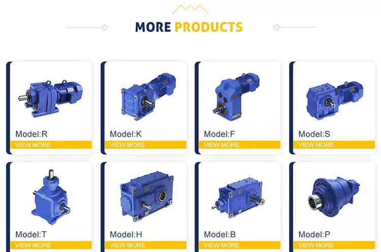
helical gear reducer
A helical gear reducer for a machine’s gearbox is an integral component of the drive system. This unit amplifies torque and controls speed and, therefore, compliments the engine by rotating slower than the engine’s input shaft. A helical gear reducer is a compact gearbox component that is used in industrial applications. A variety of sizes is available to suit various machine configurations. The following sections will discuss some of the different types available.
Designed by experts and engineers, a helical gear reducer is a surprisingly small and light gear that satisfies the needs of many machine applications. It features a large transmission torque, a low starting and running speed, and a fine classification of transmission ratios. A helical gear reducer is lightweight and easily connected to other gears, and it features a high technical content.
In order to avoid errors and poor performance, regular maintenance is a must. The proper lubrication of the gear reducer can minimize failures, errors, and poor performance. Every gear reducer manufacturer sells a suitable lubricant, which must match the properties of the machine’s drive mechanism. It is also advisable to check the lubrication regularly to avoid any deterioration of the unit’s performance.
While the worm gearbox may be better for applications where torque is high, the helical gear reducer offers greater efficiency at lower cost. Although worm gearboxes may be cheaper initially, they are less effective at higher ratios. Even if the worm gear is more expensive to buy, it still offers 94% efficiency, which makes it more cost-effective. There are some significant advantages to both types of gearboxes.
The main advantage of a helical gear reducer over a spur gear is its smoother operation. Unlike spur gears, which have teeth that are straight, helical gears have angled teeth that gradually engage with each other. This helps ensure that the gear does not grind or make excessive noise when it turns. Additionally, they are less commonly used in automation and precision machinery. They are often used in industrial applications.
Continuously variable transmission
A Continuously Variable Transmission (CVT) is an automatic transmission that can run through a vast number of gears. Unlike a standard automatic transmission, it can run at any speed, even at a low rev. The CVT is also capable of running at infinitely low gears. Its basic function is to provide different torque ratios to the engine. In addition to delivering power, CVTs have other benefits.
One of the major advantages of a CVT is its simplicity. Its simplicity translates into fewer moving parts, which means less maintenance. The CVT’s simplicity also means that it can handle a wide variety of different types of road conditions and driving styles. In addition to being a great alternative to a traditional automatic transmission, CVTs can be used on many other types of vehicles, including tractors, snowmobiles, motor scooters, and power tools.
A CVT is much smoother than a conventional automatic transmission. It never has to hunt for a gear. It also responds well to throttle inputs and speed changes. Both of these technologies are available on many modern vehicles, including the Nissan Rogue and Mazda CX-5. It’s important to note that each of these transmissions has its pros and cons. So, if you’re looking for a car with a CVT, make sure to read the reviews. They’ll help you decide which transmission is right for you.
Another advantage of a CVT is its fuel efficiency. Many cars now feature CVTs, and they’re becoming increasingly popular with automakers. In addition to fuel efficiency, most cars with CVTs also have a smoother ride. There’s no more sudden downshifts or gear hunting. This makes driving a lot easier. And, the added benefits of smoother driving make CVTs the ideal choice for many drivers.
Although a CVT is more common among Japanese car manufacturers, you’ll find CVTs on European car models as well. The Mercedes-Benz A-Class, B-Class, and Megane are some examples of vehicles that use this technology. Before making a decision, consider the reliability of the model in question. Consumer Reports is a good resource for this. It also offers a history of use and reliability for every type of car, including the Honda Accord.

