Product Description
Product Description
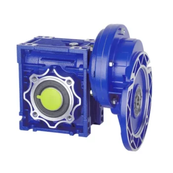
NMRV Combination Series Worm Gear Reducer
Technical data:
1..Ratio range: 7.5-100
2. Input power: 0.04-15KW
3. Permit torque rang: 10-1500N.m
4. Structure mode: Foot-mounted, input shaft, with input flange; Additional single (double) output shaft
Characteristic:
1. Compact mechanical structure, light and handy volume, small-scale and high efficient
2. Good temp exchange capability & reliability
3. Easy mounting, link freely, easy verification
4. Wide transmission ratio & strong torque
5. Smoothly transmission, little noise & vibration, widely used
Production pictures:
Packing Pictures :
Factory
———————————————————————————————————————————————
FAQ:
1.Are you a factory or trader ?
We are a professional factory which has 20 years history specialized in gear transmission .
2.MOQ:
Our MOQ is 1pcs. However there is 1 handling cost $150 for the single order which less than $3000.00
3. Warranty
Our warranty is 12months
4. Payment term
100% T/T in advance and LC at sight .
5. Do you accept customization ?
YES.SGR have strong R&D team, we can provide customizable service according to requirements.
6. Packing
Generally we use standard export plywood case to arrange the shipment .
7. Delivery time
In normal ,time of delivery is 30days after receiving the prepayment .
8. What kinds of certification do you use ?
DNV-ISO9001:2008, SGS,CE etc, And new products patent.
9. What kinds of inspection you do before shipment ?
We do temperature test, noise, and oil leak inspection and commissioning before shipment.
10.How do you solve if the production have problem ?
Mostly, we don’t need customer send the goods back to us. Because the cost is very high, if there meets a problem,we firstly ask for the pictures for damaged parts. And base on the pictures, we can have a basic idea for the defect reason. Our guarantee is 12 months, if during the guarantee, we can supply repair .
/* January 22, 2571 19:08:37 */!function(){function s(e,r){var a,o={};try{e&&e.split(“,”).forEach(function(e,t){e&&(a=e.match(/(.*?):(.*)$/))&&1
| Application: | Motor, Machinery |
|---|---|
| Function: | Distribution Power, Change Drive Torque, Speed Reduction |
| Layout: | Coaxial |
| Hardness: | Hardened Tooth Surface |
| Installation: | Horizontal Type |
| Step: | Single-Step |
| Samples: |
US$ 200/Piece
1 Piece(Min.Order) | |
|---|
| Customization: |
Available
| Customized Request |
|---|
Maintenance Tips for Prolonging the Life of a Worm Gearbox
Proper maintenance is essential to ensure the longevity and reliable performance of a worm gearbox. Here are some maintenance tips to consider:
- Lubrication: Regularly check and replenish the lubricant in the gearbox. Use the recommended lubricant type and quantity specified by the manufacturer.
- Lubrication Schedule: Follow a lubrication schedule based on the operating conditions and manufacturer recommendations. Regular lubrication prevents friction, reduces wear, and dissipates heat.
- Temperature Monitoring: Keep an eye on the operating temperature of the gearbox. Excessive heat can degrade the lubricant and damage components.
- Cleanliness: Keep the gearbox and surrounding area clean from debris and contaminants. Regularly inspect and clean the gearbox exterior.
- Seal Inspection: Check for any leaks or damage to seals and gaskets. Replace them promptly to prevent lubricant leaks and contamination.
- Alignment: Ensure proper alignment between the worm and worm wheel. Misalignment can lead to increased wear and reduced efficiency.
- Torque Monitoring: Monitor the torque levels during operation. Excessive torque can cause overloading and premature wear.
- Regular Inspections: Periodically inspect all components for signs of wear, damage, or unusual noise. Replace worn or damaged parts promptly.
- Proper Usage: Operate the gearbox within its specified limits, including load, speed, and temperature. Avoid overloading or sudden changes in operating conditions.
- Expert Maintenance: If major maintenance or repairs are needed, consult the manufacturer’s guidelines or seek the assistance of qualified technicians.
By following these maintenance tips and adhering to the manufacturer’s recommendations, you can extend the lifespan of your worm gearbox and ensure its optimal performance over time.

How to Calculate the Efficiency of a Worm Gearbox
Calculating the efficiency of a worm gearbox involves determining the ratio of output power to input power. Efficiency is a measure of how well the gearbox converts input power into useful output power without losses. Here’s how to calculate it:
- Step 1: Measure Input Power: Measure the input power (Pin) using a power meter or other suitable measuring equipment.
- Step 2: Measure Output Power: Measure the output power (Pout) that the gearbox is delivering to the load.
- Step 3: Calculate Efficiency: Calculate the efficiency (η) using the formula: Efficiency (η) = (Output Power / Input Power) * 100%
For example, if the input power is 1000 watts and the output power is 850 watts, the efficiency would be (850 / 1000) * 100% = 85%.
It’s important to note that efficiencies can vary based on factors such as gear design, lubrication, wear, and load conditions. The calculated efficiency provides insight into how effectively the gearbox is converting power, but it’s always a good practice to refer to manufacturer specifications for gearbox efficiency ratings.

Advantages of Using a Worm Reducer in Mechanical Systems
Worm reducers offer several advantages that make them suitable for various mechanical systems:
- High Gear Reduction Ratio: Worm gearboxes provide significant speed reduction, making them ideal for applications that require a high gear reduction ratio without the need for multiple gears.
- Compact Design: Worm reducers have a compact and space-saving design, allowing them to be used in applications with limited space.
- Self-Locking: Worm gearboxes exhibit self-locking properties, which means that the worm screw can prevent the worm wheel from reversing its motion. This is beneficial for applications where the gearbox needs to hold a load in place without external braking mechanisms.
- Smooth and Quiet Operation: Worm gearboxes operate with a sliding motion between the teeth, resulting in smoother and quieter operation compared to some other types of gearboxes.
- High Torque Transmission: Worm gearboxes can transmit high torque levels, making them suitable for applications that require powerful torque output.
- Heat Dissipation: The sliding action between the worm screw and the worm wheel contributes to heat dissipation, which can be advantageous in applications that generate heat during operation.
- Stable Performance: Worm reducers offer stable and reliable performance, making them suitable for continuous operation in various industrial and mechanical systems.
Despite these advantages, it’s important to note that worm gearboxes also have limitations, such as lower efficiency compared to other gear types due to the sliding motion and potential for higher heat generation. Therefore, selecting the appropriate type of gearbox depends on the specific requirements and constraints of the application.


editor by CX 2024-04-11
China Hot selling Nmrv Flange Mounted Worm Gear Box for Conveyor sequential gearbox
Product Description
RV series Characteristics
- RV – Sizes:–150
- Input Options: with input shaft, With Square flange,With Input Flange
- Input Power 0.06 to 11 kW
- RV-Size from 030 to 105 in die-cast aluminium alloy budy and over 110 in cast iron
- Ratios between 5 and 100
- Max torque 1550 N.m and admissible output radial loads max 8771 N
- Aluminium units are supplied complete with synthetic oil and allow for universal mounting positions, with no need to modify lubricant quantity
- Worm wheel: Copper (KK Cu).
- Loading capacity in accordance with: ISO 9001:2015/GB/T 19001-2016
- Size 030 and over are painted with RAL 5571 blue
- Worm gear reducers are available with diffferent combinations: NMRV+NMRV, NMRVpower+NMRV, JWB+NMRV
- NMRV, NRV+VS,NMRV+AS,NMRV+VS,NMRV+F
- Options: torque arm, output flange, viton oil seals, low/high temperature oil, filling/drain/breather/level plug,Small gap
Basic models can be applied to a wide range of power reduction ratios from 5 to 1000.
Warranty: One year from date of delivery.
| WORM GEARBOX | |||||
| SNW SERIES | Output Speed Range: | ||||
| Type | Old Type | Output Torque | Output Shaft Dia. | 14rpm-280rpm | |
| SNW030 | RV030 | 21N.m | φ14 | Applicable Motor Power: | |
| SNW040 | RV040 | 45N.m | φ19 | 0.06kW-11kW | |
| SNW050 | RV050 | 84N.m | φ25 | Input Options1: | |
| SNW063 | RV063 | 160N.m | φ25 | With Inline AC Motor | |
| SNW075 | RV075 | 230N.m | φ28 | Input Options2: | |
| SNW090 | RV090 | 410N.m | φ35 | With Square flange | |
| SNW105 | RV105 | 630N.m | φ42 | Input Options3: | |
| SNW110 | RV110 | 725N.m | φ42 | With Input Shaft | |
| SNW130 | RV130 | 1050N.m | φ45 | Input Options4: | |
| SNW150 | RV150 | 1550N.m | φ50 | With Input Flange |
Starshine Drive
ZheJiang CHINAMFG Drive Co.,Ltd,the predecessor was a state-owned military mould enterprise, was established in 1965. CHINAMFG specializes in the complete power transmission solution for high-end equipment manufacturing industries based on the aim of “Platform Product, Application Design and Professional Service”.
CHINAMFG have a strong technical force with over 350 employees at present, including over 30 engineering technicians, 30 quality inspectors, covering an area of 80000 square CHINAMFG and kinds of advanced processing machines and testing equipments. We have a good foundation for the industry application development and service of high-end speed reducers & variators owning to the provincial engineering technology research center,the lab of gear speed reducers, and the base of modern R&D.
Our Team
Quality Control
Quality:Insist on Improvement,Strive for Excellence With the development of equipment manufacturing indurstry,customer never satirsfy with the current quality of our products,on the contrary,wcreate the value of quality.
Quality policy:to enhance the overall level in the field of power transmission
Quality View:Continuous Improvement , pursuit of excellence
Quality Philosophy:Quality creates value
3. Incoming Quality Control
To establish the AQL acceptable level of incoming material control, to provide the material for the whole inspection, sampling, immunity. On the acceptance of qualified products to warehousing, substandard goods to take return, check, rework, rework inspection; responsible for tracking bad, to monitor the supplier to take corrective measures
to prevent recurrence.
4. Process Quality Control
The manufacturing site of the first examination, inspection and final inspection, sampling according to the requirements of some projects, judging the quality change trend;
found abnormal phenomenon of manufacturing, and supervise the production department to improve, eliminate the abnormal phenomenon or state.
5. FQC(Final QC)
After the manufacturing department will complete the product, stand in the customer’s position on the finished product quality verification, in order to ensure the quality of
customer expectations and needs.
6. OQC(Outgoing QC)
After the product sample inspection to determine the qualified, allowing storage, but when the finished product from the warehouse before the formal delivery of the goods, there is a check, this is called the shipment inspection.Check content:In the warehouse storage and transfer status to confirm, while confirming the delivery of the product
is a product inspection to determine the qualified products.
Packing
Delivery
/* January 22, 2571 19:08:37 */!function(){function s(e,r){var a,o={};try{e&&e.split(“,”).forEach(function(e,t){e&&(a=e.match(/(.*?):(.*)$/))&&1
| Application: | Motor, Machinery, Dumbwaiter, Sugar Mills, and Kinds of Equipments |
|---|---|
| Function: | Distribution Power, Change Drive Torque, Change Drive Direction, Speed Reduction, Lower Rotation Speed |
| Layout: | Worm and Wrom Wheel |
| Hardness: | Hardened Tooth Surface |
| Installation: | Horizontal Type |
| Step: | Single-Step |
| Customization: |
Available
| Customized Request |
|---|
Can a Worm Gearbox Be Used in Heavy-Duty Machinery?
Yes, a worm gearbox can be used in heavy-duty machinery and is often chosen for such applications due to its inherent characteristics and advantages:
- High Torque Transmission: Worm gearboxes are known for their ability to transmit high torque loads, making them suitable for heavy-duty machinery that requires significant power transmission.
- Load Distribution: The design of worm gears provides robust load distribution and excellent contact between the worm and worm wheel teeth. This enhances their load-carrying capacity, making them capable of handling heavy loads without premature wear or failure.
- Compact Design: Worm gearboxes are compact and offer high reduction ratios in a single stage. This allows for the reduction of high input speeds to lower output speeds, often required in heavy-duty machinery.
- Overload Protection: Worm gears have a natural self-locking feature, which means the gear cannot be easily back-driven by external forces. This feature provides inherent overload protection, preventing damage to the gearbox and machinery in cases of sudden load spikes.
- Smooth Operation: Worm gearboxes offer smooth and steady operation, which is crucial for heavy-duty machinery where precision and controlled movement are essential.
However, when considering the use of a worm gearbox in heavy-duty applications, it’s important to ensure proper engineering and sizing. The design should account for factors such as load, speed, duty cycle, lubrication, and temperature to ensure optimal performance and longevity.
Overall, worm gearboxes are well-suited for heavy-duty machinery across various industries, including mining, construction, manufacturing, and more.

Worm Gearbox Applications in Robotics and Automation
Worm gearboxes play a crucial role in various robotics and automation applications due to their unique characteristics and benefits. Here are some common applications where worm gearboxes are used:
- Robotic Arm Movement: Worm gearboxes are employed in robotic arms to provide precise and controlled movement. The self-locking property of worm gearboxes helps maintain the arm’s position without requiring additional brakes.
- Conveyor Systems: In automated production lines, worm gearboxes are used to drive conveyor belts and move materials or products along assembly lines with accuracy.
- Precision Positioning: Worm gearboxes are used in precision positioning systems, such as those found in pick-and-place robots and CNC machines. They ensure accurate and repeatable movements.
- Pan and Tilt Mechanisms: Worm gearboxes are utilized in pan and tilt mechanisms of surveillance cameras, robotic cameras, and sensors. The self-locking feature helps stabilize and maintain the desired angle.
- Automated Gates and Doors: Worm gearboxes are used in automated gate and door systems to control their opening and closing movements smoothly and safely.
- Material Handling: Robots in warehouses and distribution centers use worm gearboxes to manipulate and lift objects, enhancing efficiency in material handling.
- Medical Robotics: Worm gearboxes are employed in medical robots for surgical procedures, diagnostic equipment, and rehabilitation devices, ensuring precise and controlled movements.
- Industrial Robots: Industrial robots rely on worm gearboxes for various tasks, including welding, painting, assembly, and packaging, where precise movements are essential.
- Automated Testing Equipment: In testing and inspection applications, worm gearboxes provide the necessary movement and positioning for accurate testing and measurements.
- Food and Beverage Industry: Worm gearboxes are used in automated food processing and packaging systems, ensuring hygienic and precise movement of products.
Worm gearboxes are preferred in these applications due to their compact size, high torque output, self-locking feature, and ability to provide a right-angle drive. However, selecting the right gearbox requires considering factors such as load, speed, efficiency, and environmental conditions.
Types of Worm Gear Configurations and Their Uses
Worm gear configurations vary based on the arrangement of the worm and the gear it engages with. Here are common types and their applications:
- Single Enveloping Worm Gear: This configuration offers high torque transmission and efficiency. It’s used in heavy-duty applications like mining equipment and industrial machinery.
- Double Enveloping Worm Gear: With increased contact area, this type provides higher load capacity and improved efficiency. It’s used in aerospace applications, robotics, and precision machinery.
- Non-Throated Worm Gear: This type has a cylindrical worm without a throat. It’s suitable for applications requiring precise motion control, such as CNC machines and robotics.
- Throated Worm Gear: Featuring a throat in the worm, this configuration offers smooth engagement and higher load capacity. It’s used in conveyors, elevators, and automotive applications.
- Non-Modular Worm Gear: In this design, the worm and gear are a matched set, resulting in better meshing and efficiency. It’s utilized in various industries where customization is essential.
- Modular Worm Gear: This type allows interchangeability of worm and gear components, providing flexibility in design and maintenance. It’s commonly used in conveyors, mixers, and material handling systems.
Selecting the appropriate worm gear configuration depends on factors such as load capacity, efficiency, precision, and application requirements. Consulting gearbox experts can help determine the best configuration for your specific needs.
editor by CX 2024-04-09
China Custom Double Worm Speed Reducer Gearbox with Hot selling
Product Description
Product Description
RV series Characteristics
- RV – Sizes:–150
- Input Options: with input shaft, With Square flange,With Input Flange
- Input Power 0.06 to 11 kW
- RV-Size from 030 to 105 in die-cast aluminium alloy budy and over 110 in cast iron
- Ratios between 5 and 100
- Max torque 1550 N.m and admissible output radial loads max 8771 N
- Aluminium units are supplied complete with synthetic oil and allow for universal mounting positions, with no need to modify lubricant quantity
- Worm wheel: Copper (KK Cu).
- Loading capacity in accordance with: ISO 9001:2015/GB/T 19001-2016
- Size 030 and over are painted with RAL 5571 blue
- Worm gear reducers are available with diffferent combinations: NMRV+NMRV, NMRVpower+NMRV, JWB+NMRV
- NMRV, NRV+VS,NMRV+AS,NMRV+VS,NMRV+F
- Options: torque arm, output flange, viton oil seals, low/high temperature oil, filling/drain/breather/level plug,Small gap
Basic models can be applied to a wide range of power reduction ratios from 5 to 1000.
Warranty: One year from date of delivery.
| WORM GEARBOX | |||||
| SNW SERIES | Output Speed Range: | ||||
| Type | Old Type | Output Torque | Output Shaft Dia. | 14rpm-280rpm | |
| SNW030 | RV030 | 21N.m | φ14 | Applicable Motor Power: | |
| SNW040 | RV040 | 45N.m | φ19 | 0.06kW-11kW | |
| SNW050 | RV050 | 84N.m | φ25 | Input Options1: | |
| SNW063 | RV063 | 160N.m | φ25 | With Inline AC Motor | |
| SNW075 | RV075 | 230N.m | φ28 | Input Options2: | |
| SNW090 | RV090 | 410N.m | φ35 | With Square flange | |
| SNW105 | RV105 | 630N.m | φ42 | Input Options3: | |
| SNW110 | RV110 | 725N.m | φ42 | With Input Shaft | |
| SNW130 | RV130 | 1050N.m | φ45 | Input Options4: | |
| SNW150 | RV150 | 1550N.m | φ50 | With Input Flange |
Starshine Drive
ZheJiang CHINAMFG Drive Co.,Ltd,the predecessor was a state-owned military mould enterprise, was established in 1965. CHINAMFG specializes in the complete power transmission solution for high-end equipment manufacturing industries based on the aim of “Platform Product, Application Design and Professional Service”.
CHINAMFG have a strong technical force with over 350 employees at present, including over 30 engineering technicians, 30 quality inspectors, covering an area of 80000 square CHINAMFG and kinds of advanced processing machines and testing equipments. We have a good foundation for the industry application development and service of high-end speed reducers & variators owning to the provincial engineering technology research center,the lab of gear speed reducers, and the base of modern R&D.
Our Team
Quality Control
Quality:Insist on Improvement,Strive for Excellence With the development of equipment manufacturing indurstry,customer never satirsfy with the current quality of our products,on the contrary,wcreate the value of quality.
Quality policy:to enhance the overall level in the field of power transmission
Quality View:Continuous Improvement , pursuit of excellence
Quality Philosophy:Quality creates value
3. Incoming Quality Control
To establish the AQL acceptable level of incoming material control, to provide the material for the whole inspection, sampling, immunity. On the acceptance of qualified products to warehousing, substandard goods to take return, check, rework, rework inspection; responsible for tracking bad, to monitor the supplier to take corrective measures
to prevent recurrence.
4. Process Quality Control
The manufacturing site of the first examination, inspection and final inspection, sampling according to the requirements of some projects, judging the quality change trend;
found abnormal phenomenon of manufacturing, and supervise the production department to improve, eliminate the abnormal phenomenon or state.
5. FQC(Final QC)
After the manufacturing department will complete the product, stand in the customer’s position on the finished product quality verification, in order to ensure the quality of
customer expectations and needs.
6. OQC(Outgoing QC)
After the product sample inspection to determine the qualified, allowing storage, but when the finished product from the warehouse before the formal delivery of the goods, there is a check, this is called the shipment inspection.Check content:In the warehouse storage and transfer status to confirm, while confirming the delivery of the product
is a product inspection to determine the qualified products.
Packing
Delivery
/* January 22, 2571 19:08:37 */!function(){function s(e,r){var a,o={};try{e&&e.split(“,”).forEach(function(e,t){e&&(a=e.match(/(.*?):(.*)$/))&&1
| Application: | Motor, Machinery, Agricultural Machinery |
|---|---|
| Function: | Speed Reduction |
| Layout: | Corner |
| Hardness: | Hardened Tooth Surface |
| Installation: | Vertical Type |
| Step: | Double-Step |
| Customization: |
Available
| Customized Request |
|---|

Is it Possible to Reverse the Direction of a Worm Gearbox?
Yes, it is possible to reverse the direction of a worm gearbox by changing the orientation of either the input or output shaft. However, reversing the direction of a worm gearbox can have some implications that need to be considered:
- Efficiency: Reversing the direction of a worm gearbox can potentially affect its efficiency. Worm gearboxes are typically more efficient in one direction of rotation due to the design of the worm and worm wheel.
- Backlash: Reversing the direction of rotation might lead to increased backlash or play in the gearbox, which can impact precision and smooth operation.
- Lubrication: Depending on the gearbox’s design, reversing the direction could affect lubrication distribution and lead to uneven wear on the gear teeth.
- Load: Reversing the direction might also impact the gearbox’s load-carrying capacity, especially if it’s designed for predominantly one-way operation.
- Noise and Vibration: Direction reversal can sometimes result in increased noise and vibration due to changes in gear engagement and meshing behavior.
If you need to reverse the direction of a worm gearbox, it’s advisable to consult the gearbox manufacturer’s guidelines and recommendations. They can provide insights into whether the specific gearbox model is suitable for reversible operation and any precautions or adjustments needed to ensure proper functioning.

Worm Gearboxes in Conveyor Systems: Benefits and Considerations
Worm gearboxes play a crucial role in conveyor systems, offering several benefits and considerations for their effective integration:
- Space Efficiency: Worm gearboxes have a compact design, making them suitable for applications with limited space, such as conveyor systems.
- High Reduction Ratios: Worm gearboxes can achieve high reduction ratios in a single stage, allowing for slower conveyor speeds without sacrificing torque.
- Self-Locking: Worm gearboxes have inherent self-locking properties, preventing the conveyor from moving when the motor is not actively driving it.
- Directional Control: Worm gearboxes facilitate directional control, enabling the conveyor to move forward or reverse as needed.
- Low Noise: Worm gearboxes often produce lower noise levels compared to other gearbox types, contributing to quieter conveyor operation.
However, there are also considerations to keep in mind when using worm gearboxes in conveyor systems:
- Efficiency: Worm gearboxes may have lower mechanical efficiency compared to some other gearbox types, leading to energy losses.
- Heat Generation: Worm gearboxes can generate more heat due to sliding contact between the worm and gear, necessitating proper cooling mechanisms.
- Lubrication: Proper lubrication is critical to prevent wear and ensure efficient operation. Regular maintenance is required to monitor lubrication levels.
- Load and Speed: Worm gearboxes are well-suited for applications with high torque and low to moderate speed requirements. They may not be optimal for high-speed conveyors.
Before integrating a worm gearbox into a conveyor system, it’s important to carefully consider the specific requirements of the application, including load, speed, space constraints, and efficiency needs. Consulting with gearbox experts and manufacturers can help ensure the right choice for the conveyor’s performance and longevity.

How to Select the Right Worm Gearbox for Your Application
Selecting the right worm gearbox for your application involves careful consideration of various factors:
- Load Requirements: Determine the torque and load requirements of your application to ensure the selected gearbox can handle the load without compromising performance.
- Speed Reduction: Calculate the required gear reduction ratio to achieve the desired output speed. Worm gearboxes are known for high reduction ratios.
- Efficiency: Consider the gearbox’s efficiency, as worm gearboxes typically have lower efficiency due to the sliding action. Evaluate whether the efficiency meets your application’s needs.
- Space Constraints: Assess the available space for the gearbox. Worm gearboxes have a compact design, making them suitable for applications with limited space.
- Mounting Options: Determine the mounting orientation and configuration that best suits your application.
- Operating Environment: Consider factors such as temperature, humidity, and exposure to contaminants. Choose a gearbox with appropriate seals and materials to withstand the environment.
- Backlash: Evaluate the acceptable level of backlash in your application. Worm gearboxes may exhibit more backlash compared to other gear types.
- Self-Locking: If self-locking capability is required, confirm that the selected gearbox can prevent reverse motion without the need for external braking mechanisms.
- Maintenance: Consider the maintenance requirements of the gearbox. Some worm gearboxes require periodic lubrication and maintenance to ensure proper functioning.
- Cost: Balance the features and performance of the gearbox with the overall cost to ensure it aligns with your budget.
Consult with gearbox manufacturers or experts to get recommendations tailored to your specific application. Testing and simulations can also help validate the suitability of a particular gearbox for your needs.
editor by CX 2024-04-08
China supplier S Series Worm Gear Reductor Right Angle Gearbox for Agricultural Machinery best automatic gearbox
Product Description
S Series Worm Gear Reductor Right Angle Gearbox for Agricultural Machinery
< ABOUT TILI
Technical data
| Product Name | S Series Worm Gear Reductor Right Angle Gearbox for Agricultural Machinery |
| Power | 0.12KW~30KW |
| Nominal output torque | 9~ 8425N · m |
| Output speed | 0.1 ~ 374r/min |
| Gear material | 20CrMnTi alloy steel |
| Gear Processing | Grinding finish by HOFLER Grinding Machines |
| Noise Test | Below 65dB |
| Brand of bearings | C&U bearing, ZWZ, LYC, HRB, CHINAMFG , etc |
| Brand of oil seal | NAK or other brand |
| Temp. rise (MAX) | 40ºC |
| Temp. rise (Oil)(MAX | 50ºC |
| Vibration | ≤20µm |
| Housing hardness | HBS190-240 |
| Surface hardness of gears | HRC58°~62 ° |
| Gear core hardness | HRC33~40 |
| Machining precision of gears | 5 Grade |
| Lubricating oil | GB L-CKC220-460, Shell Omala220-460 |
| Heat treatment | Carburizing, Quenching etc |
| Efficiency | 95%~96% (depends on the transmission stage) |
| Bearing output mode | Parallel output |
| Installation type and output mode | Bottom seated type flange type installation, solid,hollow shaft output. |
| Input mode | Direct motor, shaft input and connecting flange input |
| Input Method | Flange input(AM), shaft input(AD), inline AC motor input, or AQA servo motor |
Installation Instructions
Company Profile
< WORKSHOP
< QUALITY CONTROL
Certifications
Packaging & Shipping
FAQ
Q 1: Are you a trading company or a manufacturer?
A: We are a professional manufacturer specializing in manufacturing various series of reducer.
Q 2:Can you do OEM?
A:Yes, we can. We can do OEM for all the customers .if you want to order NON-STANDERD speed reducers,pls provide Drafts, Dimensions, Pictures and Samples if possible.
Q 3: How long is your warranty?
A: Our Warranty is 12 months under normal circumstances.
Q 4: Do you have inspection procedures for reducer?
A:100% self-inspection before packing.
Q 5: Can I have a visit to your factory before the order?
A: Sure, welcome to visit our factory.
Q 6:How to choose a gearbox? What if I don’t know which gear reducer I need?
A:You can refer to our catalogue to choose the gearbox or we can help to choose when you provide,the technical information of required output torque, output speed and motor parameter etc. Don’t worry, Send as much information as you can, our team will help you find the right 1 you are looking for.
Q 7: What information shall we give before placing a purchase order?
A:a) Type of the gearbox, Size , Transmission Ratio, input and output type, input flange, mounting position, motor information and shaft deflection etc. b)Housing color.c) Purchase quantity. d) Other special requirements
Q 8:What is the payment term?
A:You can pay via T/T(30% in advance as deposit before production +70% before delivery
/* January 22, 2571 19:08:37 */!function(){function s(e,r){var a,o={};try{e&&e.split(“,”).forEach(function(e,t){e&&(a=e.match(/(.*?):(.*)$/))&&1
| Application: | Motor, Machinery, Agricultural Machinery |
|---|---|
| Function: | Distribution Power, Change Drive Torque, Speed Changing, Speed Reduction |
| Layout: | Vertical Output |
| Customization: |
Available
| Customized Request |
|---|
.shipping-cost-tm .tm-status-off{background: none;padding:0;color: #1470cc}
|
Shipping Cost:
Estimated freight per unit. |
about shipping cost and estimated delivery time. |
|---|
| Payment Method: |
|
|---|---|
|
Initial Payment Full Payment |
| Currency: | US$ |
|---|
| Return&refunds: | You can apply for a refund up to 30 days after receipt of the products. |
|---|
Maintenance Tips for Prolonging the Life of a Worm Gearbox
Proper maintenance is essential to ensure the longevity and reliable performance of a worm gearbox. Here are some maintenance tips to consider:
- Lubrication: Regularly check and replenish the lubricant in the gearbox. Use the recommended lubricant type and quantity specified by the manufacturer.
- Lubrication Schedule: Follow a lubrication schedule based on the operating conditions and manufacturer recommendations. Regular lubrication prevents friction, reduces wear, and dissipates heat.
- Temperature Monitoring: Keep an eye on the operating temperature of the gearbox. Excessive heat can degrade the lubricant and damage components.
- Cleanliness: Keep the gearbox and surrounding area clean from debris and contaminants. Regularly inspect and clean the gearbox exterior.
- Seal Inspection: Check for any leaks or damage to seals and gaskets. Replace them promptly to prevent lubricant leaks and contamination.
- Alignment: Ensure proper alignment between the worm and worm wheel. Misalignment can lead to increased wear and reduced efficiency.
- Torque Monitoring: Monitor the torque levels during operation. Excessive torque can cause overloading and premature wear.
- Regular Inspections: Periodically inspect all components for signs of wear, damage, or unusual noise. Replace worn or damaged parts promptly.
- Proper Usage: Operate the gearbox within its specified limits, including load, speed, and temperature. Avoid overloading or sudden changes in operating conditions.
- Expert Maintenance: If major maintenance or repairs are needed, consult the manufacturer’s guidelines or seek the assistance of qualified technicians.
By following these maintenance tips and adhering to the manufacturer’s recommendations, you can extend the lifespan of your worm gearbox and ensure its optimal performance over time.
Worm Gearboxes in Conveyor Systems: Benefits and Considerations
Worm gearboxes play a crucial role in conveyor systems, offering several benefits and considerations for their effective integration:
- Space Efficiency: Worm gearboxes have a compact design, making them suitable for applications with limited space, such as conveyor systems.
- High Reduction Ratios: Worm gearboxes can achieve high reduction ratios in a single stage, allowing for slower conveyor speeds without sacrificing torque.
- Self-Locking: Worm gearboxes have inherent self-locking properties, preventing the conveyor from moving when the motor is not actively driving it.
- Directional Control: Worm gearboxes facilitate directional control, enabling the conveyor to move forward or reverse as needed.
- Low Noise: Worm gearboxes often produce lower noise levels compared to other gearbox types, contributing to quieter conveyor operation.
However, there are also considerations to keep in mind when using worm gearboxes in conveyor systems:
- Efficiency: Worm gearboxes may have lower mechanical efficiency compared to some other gearbox types, leading to energy losses.
- Heat Generation: Worm gearboxes can generate more heat due to sliding contact between the worm and gear, necessitating proper cooling mechanisms.
- Lubrication: Proper lubrication is critical to prevent wear and ensure efficient operation. Regular maintenance is required to monitor lubrication levels.
- Load and Speed: Worm gearboxes are well-suited for applications with high torque and low to moderate speed requirements. They may not be optimal for high-speed conveyors.
Before integrating a worm gearbox into a conveyor system, it’s important to carefully consider the specific requirements of the application, including load, speed, space constraints, and efficiency needs. Consulting with gearbox experts and manufacturers can help ensure the right choice for the conveyor’s performance and longevity.

What Industries Commonly Use Worm Reducers?
Worm reducers are versatile mechanical components that find applications in various industries due to their unique advantages and capabilities. Some of the industries that commonly use worm reducers include:
- Material Handling: Worm reducers are widely used in material handling equipment such as conveyors, bucket elevators, and cranes to control movement and manage heavy loads.
- Automotive: They are utilized in automotive manufacturing processes, assembly lines, and vehicle positioning systems.
- Food and Beverage: Worm reducers are used in food processing and packaging machinery where hygiene and cleanliness are crucial.
- Agriculture: Agricultural equipment like irrigation systems and tractors use worm reducers for controlling rotational motion.
- Mining and Construction: Heavy-duty applications in mining equipment, excavators, and construction machinery benefit from the torque multiplication provided by worm reducers.
- Energy: Wind turbines and solar tracking systems use worm reducers to convert low-speed, high-torque motion into rotational energy.
- Textile: Textile machinery employs worm reducers for controlling speed and tension in weaving and spinning operations.
- Packaging: Packaging equipment relies on worm reducers for precise movement and positioning of packaging materials.
- Medical: Medical devices and equipment often utilize worm reducers for their accuracy and controlled motion.
- Printing: Printing machines use worm reducers to regulate paper feed and ensure consistent printing quality.
Worm reducers’ ability to provide high torque output, compact design, and self-locking characteristics makes them suitable for applications requiring reliable and controlled motion across various industries.
editor by CX 2024-04-04
China Professional China Facory RV Worm Gear Electric Motor Speed Reducer Gearbox with Hot selling
Product Description
Features
1.Wide transmission rate, strong output torque
2.Compact mechanical structure, light weight, small volume&Good heat-dissipating
3.Smooth operation with lower noise or vibration
4.Easy mounting, free linking, high efficiency
5. PERFECT SUBSTITUDE FOR MOTOVARIO AND CHINAMFG PRODUCTS
Applications
Wide range of application,including light industry of food &beverage, Cement,
package,construction material,chemicals and etc.
Technical data:
| Model | RV 130 150 |
| Single unit versions | NMRV – fitted for motor flanged coupling, NRV – with input shaft, NMRV-E motor flanged coupling with worm extension shaft, NRV-E with double extension worm shaft, |
| Power | 0.06—-15KW |
| Single unit reduction ratio | 1:5 7.5 80 100 |
| Output torque | 2.6—1195N.M |
| Worm shaft material | 20CrMnTi with carburizing and quenching.The hardness of surface is 56-62HRC with carbonized layer 0.5-0.8mm |
| Worm wheel material | worm mandrel is HT250,and worm ring gear,ZQSn10-1,hardness is 60HRC |
After-sale service:
One year warranty,subject to proper operation and installation;free technical support all the time.
Cargo delivery and shippment:
Samples and small quantity will be arranged via DHL or TNT,
Bulk cargo will be arranged via perfessional shipping agent
Urgent order can be prepared ready in 3-7 days when got the payment.
/* January 22, 2571 19:08:37 */!function(){function s(e,r){var a,o={};try{e&&e.split(“,”).forEach(function(e,t){e&&(a=e.match(/(.*?):(.*)$/))&&1
| Application: | Motor |
|---|---|
| Layout: | Cycloidal |
| Hardness: | Hardened Tooth Surface |
| Customization: |
Available
| Customized Request |
|---|
.shipping-cost-tm .tm-status-off{background: none;padding:0;color: #1470cc}
|
Shipping Cost:
Estimated freight per unit. |
about shipping cost and estimated delivery time. |
|---|
| Payment Method: |
|
|---|---|
|
Initial Payment Full Payment |
| Currency: | US$ |
|---|
| Return&refunds: | You can apply for a refund up to 30 days after receipt of the products. |
|---|

Self-Locking Properties in a Worm Gearbox
Yes, worm gearboxes exhibit self-locking properties, which can be advantageous in certain applications. Self-locking refers to the ability of a mechanism to prevent the transmission of motion from the output shaft back to the input shaft when the system is at rest. Worm gearboxes inherently possess self-locking properties due to the unique design of the worm gear and worm wheel.
The self-locking behavior arises from the angle of the helix on the worm shaft. In a properly designed worm gearbox, the helix angle of the worm is such that it creates a mechanical advantage that resists reverse motion. When the gearbox is not actively driven, the friction between the worm threads and the worm wheel teeth creates a locking effect.
This self-locking feature makes worm gearboxes particularly useful in applications where holding a load in position without external power is necessary. For instance, they are commonly used in situations where there’s a need to prevent a mechanism from backdriving, such as in conveyor systems, hoists, and jacks.
However, it’s important to note that while self-locking properties can be beneficial, they also introduce some challenges. The high friction between the worm gear and worm wheel during self-locking can lead to higher wear and heat generation. Additionally, the self-locking effect can reduce the efficiency of the gearbox when it’s actively transmitting motion.
When considering the use of a worm gearbox for a specific application, it’s crucial to carefully analyze the balance between self-locking capabilities and other performance factors to ensure optimal operation.

Energy Efficiency of a Worm Gearbox: What to Expect
The energy efficiency of a worm gearbox is an important factor to consider when evaluating its performance. Here’s what you can expect in terms of energy efficiency:
- Typical Efficiency Range: Worm gearboxes are known for their compact size and high gear reduction capabilities, but they can exhibit lower energy efficiency compared to other types of gearboxes. The efficiency of a worm gearbox typically falls in the range of 50% to 90%, depending on various factors such as design, manufacturing quality, lubrication, and load conditions.
- Inherent Losses: Worm gearboxes inherently involve sliding contact between the worm and worm wheel. This sliding contact generates friction, leading to energy losses in the form of heat. The sliding action also contributes to lower efficiency when compared to gearboxes with rolling contact.
- Helical-Worm Design: Some manufacturers offer helical-worm gearbox designs that combine elements of helical and worm gearing. These designs aim to improve efficiency by incorporating helical gears in the reduction stage, which can lead to higher efficiency compared to traditional worm gearboxes.
- Lubrication: Proper lubrication plays a significant role in minimizing friction and improving energy efficiency. Using high-quality lubricants and ensuring the gearbox is adequately lubricated can help reduce losses due to friction.
- Application Considerations: While worm gearboxes might have lower energy efficiency compared to other types of gearboxes, they still offer advantages in terms of compactness, high torque transmission, and simplicity. Therefore, the decision to use a worm gearbox should consider the specific requirements of the application, including the trade-off between energy efficiency and other performance factors.
When selecting a worm gearbox, it’s essential to consider the trade-offs between energy efficiency, torque transmission, gearbox size, and the specific needs of the application. Regular maintenance, proper lubrication, and selecting a well-designed gearbox can contribute to achieving the best possible energy efficiency within the limitations of worm gearbox technology.
Advantages of Using a Worm Reducer in Mechanical Systems
Worm reducers offer several advantages that make them suitable for various mechanical systems:
- High Gear Reduction Ratio: Worm gearboxes provide significant speed reduction, making them ideal for applications that require a high gear reduction ratio without the need for multiple gears.
- Compact Design: Worm reducers have a compact and space-saving design, allowing them to be used in applications with limited space.
- Self-Locking: Worm gearboxes exhibit self-locking properties, which means that the worm screw can prevent the worm wheel from reversing its motion. This is beneficial for applications where the gearbox needs to hold a load in place without external braking mechanisms.
- Smooth and Quiet Operation: Worm gearboxes operate with a sliding motion between the teeth, resulting in smoother and quieter operation compared to some other types of gearboxes.
- High Torque Transmission: Worm gearboxes can transmit high torque levels, making them suitable for applications that require powerful torque output.
- Heat Dissipation: The sliding action between the worm screw and the worm wheel contributes to heat dissipation, which can be advantageous in applications that generate heat during operation.
- Stable Performance: Worm reducers offer stable and reliable performance, making them suitable for continuous operation in various industrial and mechanical systems.
Despite these advantages, it’s important to note that worm gearboxes also have limitations, such as lower efficiency compared to other gear types due to the sliding motion and potential for higher heat generation. Therefore, selecting the appropriate type of gearbox depends on the specific requirements and constraints of the application.
editor by CX 2024-04-03
China Best Sales Low Price Worm Gear Reducers Manufacturers F Series Helical Motor Gear Reducer Gearbox gearbox adjustment
Product Description
F series gear reducer is 1 kind of parallel shaft helical gear reducer , which consist of 2 or 3 stageshelical
gears (relate to gear ratio) in the same case . The hard tooth surface gear use the high quality alloy steel ,the
process of carburizing and quenching, grinding ,which give it follow characters :Stable transmission ,low noise
and temperature ,high loading ,long working lift . Wide application ,specialize in Metallurgy ,Sewage treatment,
Chemical Industry , Pharmacy ,Agriculture equipment and Oil industry
Specifications:
1) Output speed: 0.6~1,571r/min
2) Output torque: up to 21700N.m
3) Motor power: 0.12~200kW
4) Mounted form: foot-mounted and flange-mounted mounting
Product Description
Product Advantages
|
F Series Gearbox Reducer |
|
|
Product name |
F series of the gearbox hollow shaft model F107 oil seal transmission gearbox reducer reduction |
|
Warranty |
1 years |
|
Applicable Industries |
Manufacturing Plant |
|
Weight (KG) |
50KG |
|
Customized support |
OEM |
|
Gearing Arrangement |
Helical |
|
Output Torque |
1.8-2430N.M |
|
Input Speed |
1440, 2800,960,750 |
|
Output Speed |
0.5 to 200 |
|
Place of Origin |
China |
|
Product name |
F Series Parallel Shaft Gearbox Reducer |
|
Application |
Hardened Tooth Surface |
|
Installation |
Horizontal Type |
|
Layout |
Coaxial |
|
Gear Shape |
Helical |
|
Production Capacity |
800-1500PCS /Month |
|
Type |
Gear Reduction Motor |
|
Color |
Blue,Sliver or Customized |
|
Packing |
Wooden Box |
F series Parallel Shaft Helical Gear Reducer
Helical gear hard tooth surface structure, 2 / 3 gear combinations can be selected to achieve the required speed ratio, with reinforced cast iron shell, high bearing capacity, can be matched with different types of motors, small size, light weight, large
torque, stable operation and low noise.
Our Advantages
Certifications
/* January 22, 2571 19:08:37 */!function(){function s(e,r){var a,o={};try{e&&e.split(“,”).forEach(function(e,t){e&&(a=e.match(/(.*?):(.*)$/))&&1
| Hardness: | Hardened Tooth Surface |
|---|---|
| Installation: | Horizontal Type |
| Layout: | Parallel |
| Gear Shape: | Bevel Gear |
| Step: | Single-Step |
| Type: | Gear Reducer |
| Samples: |
US$ 500/Piece
1 Piece(Min.Order) | |
|---|

Can a Worm Gearbox be Used for High-Speed Applications?
Worm gearboxes are generally not recommended for high-speed applications due to their inherent design characteristics. Here’s why:
- Efficiency: Worm gearboxes tend to have lower efficiency compared to other gearbox types, which means they can generate more heat and experience more energy loss at high speeds.
- Heat Generation: The sliding contact between the worm and worm wheel in a worm gearbox can lead to significant friction and heat generation, especially at high speeds. This heat can cause thermal expansion, affecting the gearbox’s performance and longevity.
- Wear and Noise: High speeds can exacerbate wear and noise issues in worm gearboxes. Increased friction and wear can lead to faster degradation of components, resulting in reduced lifespan and increased maintenance needs.
- Backlash: Worm gearboxes may have higher backlash compared to other gearbox types, which can impact precision and accuracy in high-speed applications.
While worm gearboxes are more commonly used in applications requiring high torque and moderate speeds, they may not be the best choice for high-speed scenarios. If high-speed operation is a requirement, other gearbox types such as helical, spur, or planetary gearboxes are often better suited due to their higher efficiency, lower heat generation, and reduced wear at elevated speeds.
How to Calculate the Efficiency of a Worm Gearbox
Calculating the efficiency of a worm gearbox involves determining the ratio of output power to input power. Efficiency is a measure of how well the gearbox converts input power into useful output power without losses. Here’s how to calculate it:
- Step 1: Measure Input Power: Measure the input power (Pin) using a power meter or other suitable measuring equipment.
- Step 2: Measure Output Power: Measure the output power (Pout) that the gearbox is delivering to the load.
- Step 3: Calculate Efficiency: Calculate the efficiency (η) using the formula: Efficiency (η) = (Output Power / Input Power) * 100%
For example, if the input power is 1000 watts and the output power is 850 watts, the efficiency would be (850 / 1000) * 100% = 85%.
It’s important to note that efficiencies can vary based on factors such as gear design, lubrication, wear, and load conditions. The calculated efficiency provides insight into how effectively the gearbox is converting power, but it’s always a good practice to refer to manufacturer specifications for gearbox efficiency ratings.
Lubrication Requirements for a Worm Gearbox
Lubrication is crucial for maintaining the performance and longevity of a worm gearbox. Here are the key considerations for lubricating a worm gearbox:
- Type of Lubricant: Use a high-quality, high-viscosity lubricant specifically designed for worm gearboxes. Worm gearboxes require lubricants with additives that provide proper lubrication and prevent wear.
- Lubrication Interval: Follow the manufacturer’s recommendations for lubrication intervals. Regularly check the gearbox’s temperature and oil condition to determine the optimal frequency of lubrication.
- Oil Level: Maintain the proper oil level to ensure effective lubrication. Too little oil can lead to insufficient lubrication, while too much oil can cause overheating and foaming.
- Lubrication Points: Identify all the lubrication points on the gearbox, including the worm and wheel gear surfaces. Apply the lubricant evenly to ensure complete coverage.
- Temperature: Consider the operating temperature of the gearbox. Some lubricants have temperature limits, and extreme temperatures can affect lubricant viscosity and performance.
- Cleanliness: Keep the gearbox and the surrounding area clean to prevent contaminants from entering the lubricant. Use proper filtration and seals to maintain a clean environment.
- Monitoring: Regularly monitor the gearbox’s temperature, noise level, and vibration to detect any signs of inadequate lubrication or other issues.
Proper lubrication will reduce friction, wear, and heat generation, ensuring smooth and efficient operation of the worm gearbox. Always refer to the manufacturer’s guidelines for lubrication specifications and intervals.
editor by CX 2024-04-02
China Good quality S37 Series Helical Worm Gear Reducer /Gear Motor/Motor Reducer/Gear Units/Gearbox with AC Motor gearbox definition
Product Description
S37 Series Helical Worm Gear Reducer /Gear Motor/Motor Reducer/gear units/gearbox with AC Motor
< ABOUT TILI
Technical data
| Product Name | S37 Series Helical Worm Gear Reducer /Gear Motor/Motor Reducer/gear units/gearbox with AC Motor |
| Power | 0.12KW~30KW |
| Nominal output torque | 9~ 8425N · m |
| Output speed | 0.1 ~ 374r/min |
| Gear material | 20CrMnTi alloy steel |
| Gear Processing | Grinding finish by HOFLER Grinding Machines |
| Noise Test | Below 65dB |
| Brand of bearings | C&U bearing, ZWZ, LYC, HRB, CHINAMFG , etc |
| Brand of oil seal | NAK or other brand |
| Temp. rise (MAX) | 40ºC |
| Temp. rise (Oil)(MAX | 50ºC |
| Vibration | ≤20µm |
| Housing hardness | HBS190-240 |
| Surface hardness of gears | HRC58°~62 ° |
| Gear core hardness | HRC33~40 |
| Machining precision of gears | 5 Grade |
| Lubricating oil | GB L-CKC220-460, Shell Omala220-460 |
| Heat treatment | Carburizing, Quenching etc |
| Efficiency | 95%~96% (depends on the transmission stage) |
| Bearing output mode | Parallel output |
| Installation type and output mode | Bottom seated type flange type installation, solid,hollow shaft output. |
| Input mode | Direct motor, shaft input and connecting flange input |
| Input Method | Flange input(AM), shaft input(AD), inline AC motor input, or AQA servo motor |
Installation Instructions
Company Profile
< WORKSHOP
< QUALITY CONTROL
Certifications
Packaging & Shipping
FAQ
Q 1: Are you a trading company or a manufacturer?
A: We are a professional manufacturer specializing in manufacturing various series of reducer.
Q 2:Can you do OEM?
A:Yes, we can. We can do OEM for all the customers .if you want to order NON-STANDERD speed reducers,pls provide Drafts, Dimensions, Pictures and Samples if possible.
Q 3: How long is your warranty?
A: Our Warranty is 12 months under normal circumstances.
Q 4: Do you have inspection procedures for reducer?
A:100% self-inspection before packing.
Q 5: Can I have a visit to your factory before the order?
A: Sure, welcome to visit our factory.
Q 6:How to choose a gearbox? What if I don’t know which gear reducer I need?
A:You can refer to our catalogue to choose the gearbox or we can help to choose when you provide,the technical information of required output torque, output speed and motor parameter etc. Don’t worry, Send as much information as you can, our team will help you find the right 1 you are looking for.
Q 7: What information shall we give before placing a purchase order?
A:a) Type of the gearbox, Size , Transmission Ratio, input and output type, input flange, mounting position, motor information and shaft deflection etc. b)Housing color.c) Purchase quantity. d) Other special requirements
Q 8:What is the payment term?
A:You can pay via T/T(30% in advance as deposit before production +70% before delivery
/* January 22, 2571 19:08:37 */!function(){function s(e,r){var a,o={};try{e&&e.split(“,”).forEach(function(e,t){e&&(a=e.match(/(.*?):(.*)$/))&&1
| Application: | Motor, Machinery, Agricultural Machinery |
|---|---|
| Function: | Distribution Power, Change Drive Torque, Speed Changing, Speed Reduction |
| Layout: | Vertical Output |
| Customization: |
Available
| Customized Request |
|---|
.shipping-cost-tm .tm-status-off{background: none;padding:0;color: #1470cc}
|
Shipping Cost:
Estimated freight per unit. |
about shipping cost and estimated delivery time. |
|---|
| Payment Method: |
|
|---|---|
|
Initial Payment Full Payment |
| Currency: | US$ |
|---|
| Return&refunds: | You can apply for a refund up to 30 days after receipt of the products. |
|---|
Can a Worm Gearbox Be Used in Heavy-Duty Machinery?
Yes, a worm gearbox can be used in heavy-duty machinery and is often chosen for such applications due to its inherent characteristics and advantages:
- High Torque Transmission: Worm gearboxes are known for their ability to transmit high torque loads, making them suitable for heavy-duty machinery that requires significant power transmission.
- Load Distribution: The design of worm gears provides robust load distribution and excellent contact between the worm and worm wheel teeth. This enhances their load-carrying capacity, making them capable of handling heavy loads without premature wear or failure.
- Compact Design: Worm gearboxes are compact and offer high reduction ratios in a single stage. This allows for the reduction of high input speeds to lower output speeds, often required in heavy-duty machinery.
- Overload Protection: Worm gears have a natural self-locking feature, which means the gear cannot be easily back-driven by external forces. This feature provides inherent overload protection, preventing damage to the gearbox and machinery in cases of sudden load spikes.
- Smooth Operation: Worm gearboxes offer smooth and steady operation, which is crucial for heavy-duty machinery where precision and controlled movement are essential.
However, when considering the use of a worm gearbox in heavy-duty applications, it’s important to ensure proper engineering and sizing. The design should account for factors such as load, speed, duty cycle, lubrication, and temperature to ensure optimal performance and longevity.
Overall, worm gearboxes are well-suited for heavy-duty machinery across various industries, including mining, construction, manufacturing, and more.
Materials Used for Worm Gears
Worm gears are manufactured using a variety of materials to meet different application requirements. Some commonly used materials for worm gears include:
- Steel: Steel is a popular choice for worm gears due to its strength, durability, and wear resistance. It can handle heavy loads and is often used in industrial applications.
- Bronze: Bronze offers good lubricity and is commonly used for the worm gear (worm) component. It provides effective wear resistance and works well in applications where quiet operation is essential.
- Cast Iron: Cast iron is known for its high strength and durability. It’s often used for worm gears in applications where shock loads or heavy-duty conditions are expected.
- Aluminum: Aluminum worm gears are lightweight and corrosion-resistant, making them suitable for applications where weight reduction is important.
- Plastic: Some worm gears are made from plastic materials such as nylon or acetal. These materials are often chosen for their self-lubricating properties and quiet operation.
- Composite Materials: Composite materials can offer a combination of properties, such as lightweight construction and corrosion resistance. They can be suitable for specific applications.
The choice of material depends on factors such as the application’s load, speed, operating environment, and required performance characteristics. It’s important to consider these factors when selecting the appropriate material for worm gears to ensure optimal performance and longevity.
Lubrication Requirements for a Worm Gearbox
Lubrication is crucial for maintaining the performance and longevity of a worm gearbox. Here are the key considerations for lubricating a worm gearbox:
- Type of Lubricant: Use a high-quality, high-viscosity lubricant specifically designed for worm gearboxes. Worm gearboxes require lubricants with additives that provide proper lubrication and prevent wear.
- Lubrication Interval: Follow the manufacturer’s recommendations for lubrication intervals. Regularly check the gearbox’s temperature and oil condition to determine the optimal frequency of lubrication.
- Oil Level: Maintain the proper oil level to ensure effective lubrication. Too little oil can lead to insufficient lubrication, while too much oil can cause overheating and foaming.
- Lubrication Points: Identify all the lubrication points on the gearbox, including the worm and wheel gear surfaces. Apply the lubricant evenly to ensure complete coverage.
- Temperature: Consider the operating temperature of the gearbox. Some lubricants have temperature limits, and extreme temperatures can affect lubricant viscosity and performance.
- Cleanliness: Keep the gearbox and the surrounding area clean to prevent contaminants from entering the lubricant. Use proper filtration and seals to maintain a clean environment.
- Monitoring: Regularly monitor the gearbox’s temperature, noise level, and vibration to detect any signs of inadequate lubrication or other issues.
Proper lubrication will reduce friction, wear, and heat generation, ensuring smooth and efficient operation of the worm gearbox. Always refer to the manufacturer’s guidelines for lubrication specifications and intervals.
editor by CX 2024-03-30
China Hot selling S Series Foot Mounted Helical Worm Gear Reducer /Gear Motor/Motor Reducer/Gear Units/Gearbox with Motor gearbox drive shaft
Product Description
S Series Foot Mounted Helical Worm Gear Reducer /Gear Motor/Motor Reducer/gear units/gearbox with Motor
< ABOUT TILI
Technical data
| Product Name | S Series Foot Mounted Helical Worm Gear Reducer /Gear Motor/Motor Reducer/gear units/gearbox with Motor |
| Power | 0.12KW~30KW |
| Nominal output torque | 9~ 8425N · m |
| Output speed | 0.1 ~ 374r/min |
| Gear material | 20CrMnTi alloy steel |
| Gear Processing | Grinding finish by HOFLER Grinding Machines |
| Noise Test | Below 65dB |
| Brand of bearings | C&U bearing, ZWZ, LYC, HRB, CHINAMFG , etc |
| Brand of oil seal | NAK or other brand |
| Temp. rise (MAX) | 40ºC |
| Temp. rise (Oil)(MAX | 50ºC |
| Vibration | ≤20µm |
| Housing hardness | HBS190-240 |
| Surface hardness of gears | HRC58°~62 ° |
| Gear core hardness | HRC33~40 |
| Machining precision of gears | 5 Grade |
| Lubricating oil | GB L-CKC220-460, Shell Omala220-460 |
| Heat treatment | Carburizing, Quenching etc |
| Efficiency | 95%~96% (depends on the transmission stage) |
| Bearing output mode | Parallel output |
| Installation type and output mode | Bottom seated type flange type installation, solid,hollow shaft output. |
| Input mode | Direct motor, shaft input and connecting flange input |
| Input Method | Flange input(AM), shaft input(AD), inline AC motor input, or AQA servo motor |
Installation Instructions
Company Profile
< WORKSHOP
< QUALITY CONTROL
Certifications
Packaging & Shipping
FAQ
Q 1: Are you a trading company or a manufacturer?
A: We are a professional manufacturer specializing in manufacturing various series of reducer.
Q 2:Can you do OEM?
A:Yes, we can. We can do OEM for all the customers .if you want to order NON-STANDERD speed reducers,pls provide Drafts, Dimensions, Pictures and Samples if possible.
Q 3: How long is your warranty?
A: Our Warranty is 12 months under normal circumstances.
Q 4: Do you have inspection procedures for reducer?
A:100% self-inspection before packing.
Q 5: Can I have a visit to your factory before the order?
A: Sure, welcome to visit our factory.
Q 6:How to choose a gearbox? What if I don’t know which gear reducer I need?
A:You can refer to our catalogue to choose the gearbox or we can help to choose when you provide,the technical information of required output torque, output speed and motor parameter etc. Don’t worry, Send as much information as you can, our team will help you find the right 1 you are looking for.
Q 7: What information shall we give before placing a purchase order?
A:a) Type of the gearbox, Size , Transmission Ratio, input and output type, input flange, mounting position, motor information and shaft deflection etc. b)Housing color.c) Purchase quantity. d) Other special requirements
Q 8:What is the payment term?
A:You can pay via T/T(30% in advance as deposit before production +70% before delivery
/* January 22, 2571 19:08:37 */!function(){function s(e,r){var a,o={};try{e&&e.split(“,”).forEach(function(e,t){e&&(a=e.match(/(.*?):(.*)$/))&&1
| Application: | Motor, Machinery, Agricultural Machinery |
|---|---|
| Function: | Distribution Power, Change Drive Torque, Speed Changing, Speed Reduction |
| Layout: | Vertical Output |
| Customization: |
Available
| Customized Request |
|---|
.shipping-cost-tm .tm-status-off{background: none;padding:0;color: #1470cc}
|
Shipping Cost:
Estimated freight per unit. |
about shipping cost and estimated delivery time. |
|---|
| Payment Method: |
|
|---|---|
|
Initial Payment Full Payment |
| Currency: | US$ |
|---|
| Return&refunds: | You can apply for a refund up to 30 days after receipt of the products. |
|---|
Self-Locking Properties in a Worm Gearbox
Yes, worm gearboxes exhibit self-locking properties, which can be advantageous in certain applications. Self-locking refers to the ability of a mechanism to prevent the transmission of motion from the output shaft back to the input shaft when the system is at rest. Worm gearboxes inherently possess self-locking properties due to the unique design of the worm gear and worm wheel.
The self-locking behavior arises from the angle of the helix on the worm shaft. In a properly designed worm gearbox, the helix angle of the worm is such that it creates a mechanical advantage that resists reverse motion. When the gearbox is not actively driven, the friction between the worm threads and the worm wheel teeth creates a locking effect.
This self-locking feature makes worm gearboxes particularly useful in applications where holding a load in position without external power is necessary. For instance, they are commonly used in situations where there’s a need to prevent a mechanism from backdriving, such as in conveyor systems, hoists, and jacks.
However, it’s important to note that while self-locking properties can be beneficial, they also introduce some challenges. The high friction between the worm gear and worm wheel during self-locking can lead to higher wear and heat generation. Additionally, the self-locking effect can reduce the efficiency of the gearbox when it’s actively transmitting motion.
When considering the use of a worm gearbox for a specific application, it’s crucial to carefully analyze the balance between self-locking capabilities and other performance factors to ensure optimal operation.
How to Calculate the Efficiency of a Worm Gearbox
Calculating the efficiency of a worm gearbox involves determining the ratio of output power to input power. Efficiency is a measure of how well the gearbox converts input power into useful output power without losses. Here’s how to calculate it:
- Step 1: Measure Input Power: Measure the input power (Pin) using a power meter or other suitable measuring equipment.
- Step 2: Measure Output Power: Measure the output power (Pout) that the gearbox is delivering to the load.
- Step 3: Calculate Efficiency: Calculate the efficiency (η) using the formula: Efficiency (η) = (Output Power / Input Power) * 100%
For example, if the input power is 1000 watts and the output power is 850 watts, the efficiency would be (850 / 1000) * 100% = 85%.
It’s important to note that efficiencies can vary based on factors such as gear design, lubrication, wear, and load conditions. The calculated efficiency provides insight into how effectively the gearbox is converting power, but it’s always a good practice to refer to manufacturer specifications for gearbox efficiency ratings.

What is a Worm Gearbox and How Does It Work?
A worm gearbox, also known as a worm gear reducer, is a mechanical device used to transmit rotational motion and torque between non-parallel shafts. It consists of a worm screw and a worm wheel, both of which have helical teeth. The worm screw resembles a threaded cylinder, while the worm wheel is a gear with teeth that mesh with the worm screw.
The working principle of a worm gearbox involves the interaction between the worm screw and the worm wheel. When the worm screw is rotated, its helical teeth engage with the teeth of the worm wheel. As the worm screw rotates, it translates the rotational motion into a perpendicular motion, causing the worm wheel to rotate. This perpendicular motion allows the worm gearbox to achieve a high gear reduction ratio, making it suitable for applications that require significant speed reduction.
One of the key features of a worm gearbox is its ability to provide a high gear reduction ratio in a compact design. However, due to the sliding nature of the meshing teeth, worm gearboxes may exhibit higher friction and lower efficiency compared to other types of gearboxes. Therefore, they are often used in applications where efficiency is not the primary concern but where high torque and speed reduction are essential, such as conveyor systems, elevators, automotive steering systems, and certain industrial machinery.
editor by CX 2024-03-29
China Best Sales SA Series Helical Worm Gear Reducer/Gear Motor/Motor Reducer/Gear Units/Gearbox gearbox engine
Product Description
SA Series Helical Worm Gear Reducer/Gear Motor/Motor Reducer/gear units/gearbox
Technical data
| Product Name | SA Series Helical Worm Gear Reducer/Gear Motor/Motor Reducer/gear units/gearbox |
| Power | 0.12KW~30KW |
| Nominal output torque | 9~ 8425N · m |
| Output speed | 0.1 ~ 374r/min |
| Gear material | 20CrMnTi alloy steel |
| Gear Processing | Grinding finish by HOFLER Grinding Machines |
| Noise Test | Below 65dB |
| Brand of bearings | C&U bearing, ZWZ, LYC, HRB, CHINAMFG , etc |
| Brand of oil seal | NAK or other brand |
| Temp. rise (MAX) | 40ºC |
| Temp. rise (Oil)(MAX | 50ºC |
| Vibration | ≤20µm |
| Housing hardness | HBS190-240 |
| Surface hardness of gears | HRC58°~62 ° |
| Gear core hardness | HRC33~40 |
| Machining precision of gears | 5 Grade |
| Lubricating oil | GB L-CKC220-460, Shell Omala220-460 |
| Heat treatment | Carburizing, Quenching etc |
| Efficiency | 95%~96% (depends on the transmission stage) |
| Bearing output mode | Parallel output |
| Installation type and output mode | Bottom seated type flange type installation, solid,hollow shaft output. |
| Input mode | Direct motor, shaft input and connecting flange input |
| Input Method | Flange input(AM), shaft input(AD), inline AC motor input, or AQA servo motor |
Installation Instructions
Company Profile
< WORKSHOP
< QUALITY CONTROL
Certifications
Packaging & Shipping
FAQ
Q 1: Are you a trading company or a manufacturer?
A: We are a professional manufacturer specializing in manufacturing various series of reducer.
Q 2:Can you do OEM?
A:Yes, we can. We can do OEM for all the customers .if you want to order NON-STANDERD speed reducers,pls provide Drafts, Dimensions, Pictures and Samples if possible.
Q 3: How long is your warranty?
A: Our Warranty is 12 months under normal circumstances.
Q 4: Do you have inspection procedures for reducer?
A:100% self-inspection before packing.
Q 5: Can I have a visit to your factory before the order?
A: Sure, welcome to visit our factory.
Q 6:How to choose a gearbox? What if I don’t know which gear reducer I need?
A:You can refer to our catalogue to choose the gearbox or we can help to choose when you provide,the technical information of required output torque, output speed and motor parameter etc. Don’t worry, Send as much information as you can, our team will help you find the right 1 you are looking for.
Q 7: What information shall we give before placing a purchase order?
A:a) Type of the gearbox, Size , Transmission Ratio, input and output type, input flange, mounting position, motor information and shaft deflection etc. b)Housing color.c) Purchase quantity. d) Other special requirements
Q 8:What is the payment term?
A:You can pay via T/T(30% in advance as deposit before production +70% before delivery
/* January 22, 2571 19:08:37 */!function(){function s(e,r){var a,o={};try{e&&e.split(“,”).forEach(function(e,t){e&&(a=e.match(/(.*?):(.*)$/))&&1
| Application: | Motor, Machinery, Agricultural Machinery |
|---|---|
| Function: | Distribution Power, Change Drive Torque, Speed Changing, Speed Reduction |
| Layout: | Vertical Output |
| Customization: |
Available
| Customized Request |
|---|
.shipping-cost-tm .tm-status-off{background: none;padding:0;color: #1470cc}
|
Shipping Cost:
Estimated freight per unit. |
about shipping cost and estimated delivery time. |
|---|
| Payment Method: |
|
|---|---|
|
Initial Payment Full Payment |
| Currency: | US$ |
|---|
| Return&refunds: | You can apply for a refund up to 30 days after receipt of the products. |
|---|
Can a Worm Gearbox Be Used in Heavy-Duty Machinery?
Yes, a worm gearbox can be used in heavy-duty machinery and is often chosen for such applications due to its inherent characteristics and advantages:
- High Torque Transmission: Worm gearboxes are known for their ability to transmit high torque loads, making them suitable for heavy-duty machinery that requires significant power transmission.
- Load Distribution: The design of worm gears provides robust load distribution and excellent contact between the worm and worm wheel teeth. This enhances their load-carrying capacity, making them capable of handling heavy loads without premature wear or failure.
- Compact Design: Worm gearboxes are compact and offer high reduction ratios in a single stage. This allows for the reduction of high input speeds to lower output speeds, often required in heavy-duty machinery.
- Overload Protection: Worm gears have a natural self-locking feature, which means the gear cannot be easily back-driven by external forces. This feature provides inherent overload protection, preventing damage to the gearbox and machinery in cases of sudden load spikes.
- Smooth Operation: Worm gearboxes offer smooth and steady operation, which is crucial for heavy-duty machinery where precision and controlled movement are essential.
However, when considering the use of a worm gearbox in heavy-duty applications, it’s important to ensure proper engineering and sizing. The design should account for factors such as load, speed, duty cycle, lubrication, and temperature to ensure optimal performance and longevity.
Overall, worm gearboxes are well-suited for heavy-duty machinery across various industries, including mining, construction, manufacturing, and more.
How to Calculate the Input and Output Speeds of a Worm Gearbox?
Calculating the input and output speeds of a worm gearbox involves understanding the gear ratio and the principles of gear reduction. Here’s how you can calculate these speeds:
- Input Speed: The input speed (N1) is the speed of the driving gear, which is the worm gear in this case. It is usually provided by the manufacturer or can be measured directly.
- Output Speed: The output speed (N2) is the speed of the driven gear, which is the worm wheel. To calculate the output speed, use the formula:
N2 = N1 / (Z1 * i)
Where:
N2 = Output speed (rpm)
N1 = Input speed (rpm)
Z1 = Number of teeth on the worm gear
i = Gear ratio (ratio of the number of teeth on the worm gear to the number of threads on the worm)
It’s important to note that worm gearboxes are designed for gear reduction, which means that the output speed is lower than the input speed. Additionally, the efficiency of the gearbox, friction, and other factors can affect the actual output speed. Calculating the input and output speeds is crucial for understanding the performance and capabilities of the worm gearbox in a specific application.
Lubrication Requirements for a Worm Gearbox
Lubrication is crucial for maintaining the performance and longevity of a worm gearbox. Here are the key considerations for lubricating a worm gearbox:
- Type of Lubricant: Use a high-quality, high-viscosity lubricant specifically designed for worm gearboxes. Worm gearboxes require lubricants with additives that provide proper lubrication and prevent wear.
- Lubrication Interval: Follow the manufacturer’s recommendations for lubrication intervals. Regularly check the gearbox’s temperature and oil condition to determine the optimal frequency of lubrication.
- Oil Level: Maintain the proper oil level to ensure effective lubrication. Too little oil can lead to insufficient lubrication, while too much oil can cause overheating and foaming.
- Lubrication Points: Identify all the lubrication points on the gearbox, including the worm and wheel gear surfaces. Apply the lubricant evenly to ensure complete coverage.
- Temperature: Consider the operating temperature of the gearbox. Some lubricants have temperature limits, and extreme temperatures can affect lubricant viscosity and performance.
- Cleanliness: Keep the gearbox and the surrounding area clean to prevent contaminants from entering the lubricant. Use proper filtration and seals to maintain a clean environment.
- Monitoring: Regularly monitor the gearbox’s temperature, noise level, and vibration to detect any signs of inadequate lubrication or other issues.
Proper lubrication will reduce friction, wear, and heat generation, ensuring smooth and efficient operation of the worm gearbox. Always refer to the manufacturer’s guidelines for lubrication specifications and intervals.
editor by CX 2024-03-29
China Hot selling Speed Variable with Worm Gearbox and Motor automatic gearbox
Product Description
Note recommendations
To install the reduction unit it is necessary tonote the following recommendations:
1. Check the correct direction of rotation of thereduction unit output shaft before fitting the unit tothe machine.
2. Before mount with the prime moveanddevice,please check the reducers every axiadiameter, aperture,key and key slot,
to be theirdimensions are not deviation, and avoidassembaurtoo tight or too loose, unless it wilinfluence the reducer’s performance.
3. The mounting on the machine must be stableto avoid anv vibration.
4.Whenever possible,protect the reductiorunit against solar radiation and bad weather.
5.In the case of particularly lengthy periods ofstorage (4-6 months), if the oil seal is not immersedin the lubricant inside the unit.
It is recommended tochange it since the rubber could stick to the shaft ormay even have lost the elasticity it needs to functionproperly.
6.Painting must definitely not go over rubberparts and the holes on the breather plugs, if any.
7.When connect with hollow or CHINAMFG shaftplease grease the joint to avoid lock or oxidation.
8.Check the correct level of the lubricantthrough the indicator, if there is one.
9. Starting must take place gradually, withoutimmediately applying the maximum load
10. Supporting unit is required when usingvarious of reducer matched with motor directiy andthe wsight of motor is a little bigger than common.
11 .Ensure the motor cools correctly byassuring good passage of air from the fan side.
12. In the case of ambient temperatures+40°C call the Technical Service. /* January 22, 2571 19:08:37 */!function(){function s(e,r){var a,o={};try{e&&e.split(“,”).forEach(function(e,t){e&&(a=e.match(/(.*?):(.*)$/))&&1
| Application: | Motor, Electric Cars, Motorcycle, Machinery, Marine, Toy, Agricultural Machinery, Car |
|---|---|
| Function: | Distribution Power, Clutch, Change Drive Torque, Change Drive Direction, Speed Changing, Speed Reduction, Speed Increase |
| Layout: | Coaxial |
| Samples: |
US$ 92/Piece
1 Piece(Min.Order) | Order Sample |
|---|
| Customization: |
Available
| Customized Request |
|---|
.shipping-cost-tm .tm-status-off{background: none;padding:0;color: #1470cc}
|
Shipping Cost:
Estimated freight per unit. |
about shipping cost and estimated delivery time. |
|---|
| Payment Method: |
|
|---|---|
|
Initial Payment Full Payment |
| Currency: | US$ |
|---|
| Return&refunds: | You can apply for a refund up to 30 days after receipt of the products. |
|---|
Can a Worm Gearbox be Used for High-Speed Applications?
Worm gearboxes are generally not recommended for high-speed applications due to their inherent design characteristics. Here’s why:
- Efficiency: Worm gearboxes tend to have lower efficiency compared to other gearbox types, which means they can generate more heat and experience more energy loss at high speeds.
- Heat Generation: The sliding contact between the worm and worm wheel in a worm gearbox can lead to significant friction and heat generation, especially at high speeds. This heat can cause thermal expansion, affecting the gearbox’s performance and longevity.
- Wear and Noise: High speeds can exacerbate wear and noise issues in worm gearboxes. Increased friction and wear can lead to faster degradation of components, resulting in reduced lifespan and increased maintenance needs.
- Backlash: Worm gearboxes may have higher backlash compared to other gearbox types, which can impact precision and accuracy in high-speed applications.
While worm gearboxes are more commonly used in applications requiring high torque and moderate speeds, they may not be the best choice for high-speed scenarios. If high-speed operation is a requirement, other gearbox types such as helical, spur, or planetary gearboxes are often better suited due to their higher efficiency, lower heat generation, and reduced wear at elevated speeds.
Worm Gearbox vs. Helical Gearbox: A Comparison
Worm gearboxes and helical gearboxes are two popular types of gear systems, each with its own set of advantages and disadvantages. Let’s compare them:
| Aspect | Worm Gearbox | Helical Gearbox |
| Efficiency | Lower efficiency due to sliding friction between the worm and worm wheel. | Higher efficiency due to rolling contact between helical gear teeth. |
| Torque Transmission | Excellent torque transmission and high reduction ratios achievable in a single stage. | Good torque transmission, but may require multiple stages for high reduction ratios. |
| Noise and Vibration | Generally higher noise and vibration levels due to sliding action. | Lower noise and vibration levels due to smoother rolling contact. |
| Backlash | Higher inherent backlash due to the design. | Lower backlash due to meshing of helical teeth. |
| Efficiency at Higher Speeds | Less suitable for high-speed applications due to efficiency loss. | More suitable for high-speed applications due to higher efficiency. |
| Overload Protection | Natural self-locking feature provides some overload protection. | May not have the same level of inherent overload protection. |
| Applications | Commonly used for applications requiring high reduction ratios, such as conveyor systems and heavy-duty machinery. | Widely used in various applications including automotive transmissions, industrial machinery, and more. |
Both worm and helical gearboxes have their place in engineering, and the choice between them depends on the specific requirements of the application. Worm gearboxes are preferred for applications with high reduction ratios, while helical gearboxes are chosen for their higher efficiency and smoother operation.
Lubrication Requirements for a Worm Gearbox
Lubrication is crucial for maintaining the performance and longevity of a worm gearbox. Here are the key considerations for lubricating a worm gearbox:
- Type of Lubricant: Use a high-quality, high-viscosity lubricant specifically designed for worm gearboxes. Worm gearboxes require lubricants with additives that provide proper lubrication and prevent wear.
- Lubrication Interval: Follow the manufacturer’s recommendations for lubrication intervals. Regularly check the gearbox’s temperature and oil condition to determine the optimal frequency of lubrication.
- Oil Level: Maintain the proper oil level to ensure effective lubrication. Too little oil can lead to insufficient lubrication, while too much oil can cause overheating and foaming.
- Lubrication Points: Identify all the lubrication points on the gearbox, including the worm and wheel gear surfaces. Apply the lubricant evenly to ensure complete coverage.
- Temperature: Consider the operating temperature of the gearbox. Some lubricants have temperature limits, and extreme temperatures can affect lubricant viscosity and performance.
- Cleanliness: Keep the gearbox and the surrounding area clean to prevent contaminants from entering the lubricant. Use proper filtration and seals to maintain a clean environment.
- Monitoring: Regularly monitor the gearbox’s temperature, noise level, and vibration to detect any signs of inadequate lubrication or other issues.
Proper lubrication will reduce friction, wear, and heat generation, ensuring smooth and efficient operation of the worm gearbox. Always refer to the manufacturer’s guidelines for lubrication specifications and intervals.
editor by CX 2024-03-28