Опис
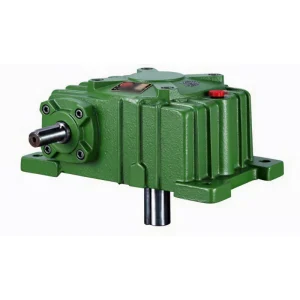
WPWE Flange-Base Double Speed Worm Gear Reducer — Ultra-High Ratio Two-Stage Drive with Integral Flange Mounting Base
Large-scale stirring vessels, heavy rotary kilns, and robust process equipment drives face a recurring challenge: a two-stage gearbox providing ultra-high reduction ratios must be mounted securely enough to withstand the high torque reactions of 1/600–1/900 combined ratio operation without transmitting vibration to the supporting structure. The WPWE flange-base double speed worm gear reducer addresses this with an integral flanged base that distributes mounting forces over a larger bearing surface compared to the standard foot-mount WPEA series.
The WPWE two-stage housing incorporates AC, BC (flange offset), and AD, BD (bolt pattern) dimensions that provide a rigid, bolt-down connection suitable for mounting directly onto machine base frames, vessel pedestals, and structural steelwork. Available in 9 size groups (40-70 through 155-250), ratios 1/200–1/900, 5 shaft-direction positions. The Z×L column in the specification table defines the foundation bolt specification for each size group. Про Ever-power | Request a Selection Guide
Technical Specifications
Full dimensional data for all WPWE sizes. AC, BC = flange arm dimensions; AD, BD = bolt hole positions; Z×L = anchor bolt specification (e.g. M16×35 = M16 bolt, 35 mm deep). HH = lateral height; HL = housing height; LL = housing length. Reference input speed 1500 r/min. All dimensions in mm.

| Size | Ratio | A | AA | AB | BB | BE | AC | BC | AD | BD | HH | HL | LL | H | Z×L | HS | U | T×V | LS | S | W×Y | Wt(kg) |
|---|---|---|---|---|---|---|---|---|---|---|---|---|---|---|---|---|---|---|---|---|---|---|
| 40-70 | 1/200–1/900 | 286 | 195 | 153 | 131 | 87 | 152 | 86 | 125 | 65 | 35 | 200 | 90 | 215 | M10×25 | 25 | 12 | 4×2.5 | 60 | 28 | 7×4 | 19 |
| 50-80 | 297 | 197 | 144 | 142 | 108 | 169 | 102 | 140 | 70 | 35 | 235 | 105 | 250 | M12×28 | 30 | 12 | 4×2.5 | 65 | 32 | 10×4.5 | 28 | |
| 60-100 | 363 | 231 | 175 | 169 | 120 | 216 | 117 | 180 | 90 | 42 | 290 | 130 | 310 | M12×30 | 40 | 15 | 5×3 | 75 | 38 | 10×4.5 | 43 | |
| 70-120 | 408 | 256 | 193 | 190 | 140 | 256 | 124 | 220 | 100 | 55 | 345 | 155 | 370 | M14×32 | 40 | 18 | 5×3 | 85 | 45 | 14×4.8 | 64 | |
| 80-135 | 471 | 298 | 226 | 210 | 160 | 296 | 147 | 260 | 110 | 65 | 400 | 185 | 425 | M16×35 | 50 | 22 | 7×4 | 95 | 55 | 16×6 | 99 | |
| 100-155 | 555 | 354 | 269 | 252 | 190 | 345 | 185 | 280 | 120 | 80 | 458 | 203 | 461 | M16×35 | 50 | 25 | 7×4 | 110 | 60 | 18×7 | 136 | |
| 120-175 | 598 | 379 | 287 | 282 | 219 | 374 | 192 | 320 | 140 | 95 | 518 | 223 | 521 | M16×35 | 65 | 30 | 7×4 | 110 | 65 | 18×7 | 193 | |
| 135-200 | 662 | 425 | 318 | 319 | 256 | 412 | 230 | 360 | 150 | 105 | 580 | 245 | 575 | M20×36 | 75 | 35 | 10×5 | 125 | 70 | 20×7.5 | 280 | |
| 155-250 | 795 | 510 | 380 | 385 | 295 | 500 | 285 | 420 | 190 | 103 | 705 | 300 | 700 | M24×42 | 85 | 40 | 12×5 | 155 | 90 | 25×9 | 442 |
* Z×L = foundation bolt specification. AC and BC define the flange arm geometry; AD and BD define the bolt hole spacing from housing centreline. The flanged base provides greater installation rigidity than foot-mount WPEA equivalents for high-torque two-stage applications.
Product Structure — Two-Stage Housing with Integral Flange Base
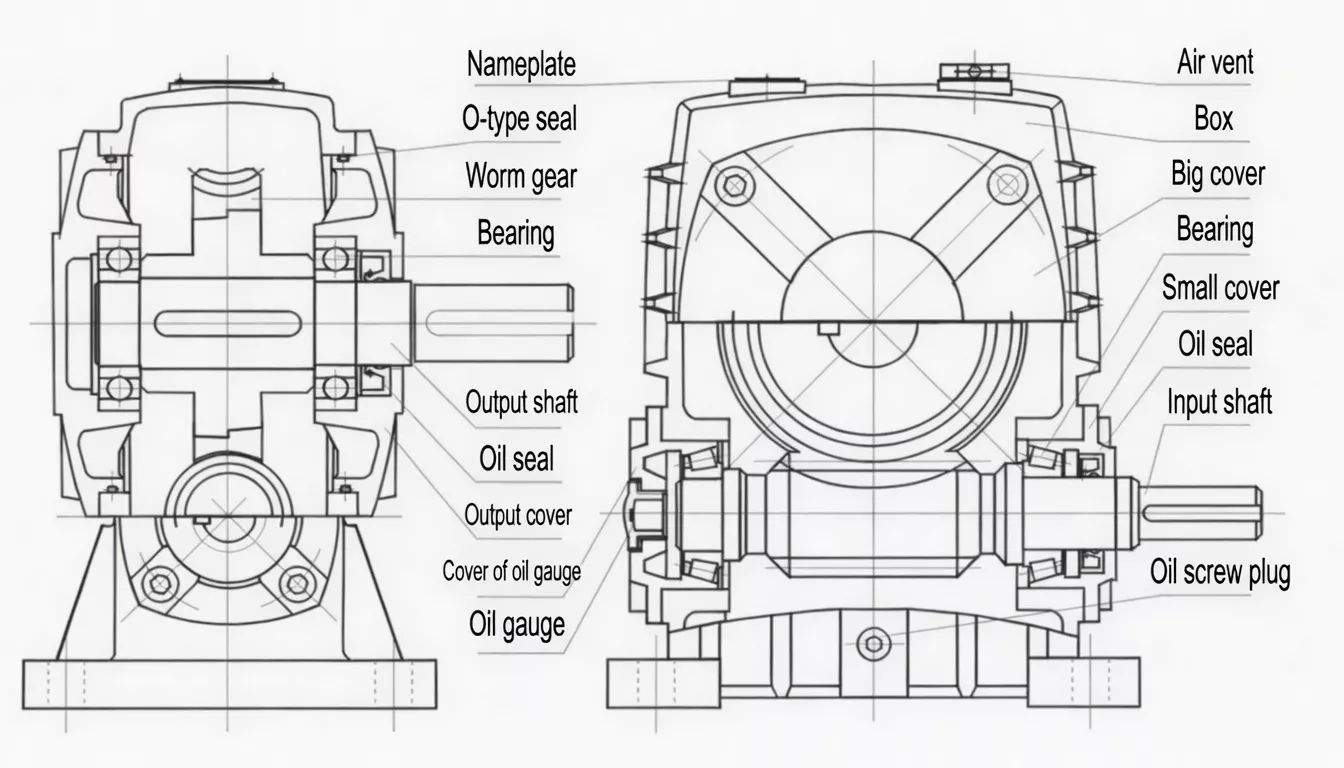
The WPWE integrates the same two-worm-pair cascade as the WPEA with a wider, flanged base section that extends laterally beyond the housing sides. This flanged base provides multiple bolt-down points that distribute the reaction torque of the two-stage gear system over a larger area — reducing concentrated stresses at individual mounting points and providing a more stable, vibration-resistant installation. The base surface is precision-machined for flat contact with the mounting structure.
| Stages | Two worm-and-wheel pairs in series; ratio 1/200–1/900 |
| Base Type | Integral flanged base with multiple anchor bolt positions (Z×L per size) |
| Base Machining | Precision-machined flat base surface; ≤0.05 mm flatness tolerance |
| Housing | FC25 cast iron; wider body than WPEA to accommodate flange arms |
| Worm Pairs | 20CrMnTi (≥58 HRC) + ZCuSn10Pb1 bronze; both stages |
| Shaft Positions | 5 configurable orientations: A, B, C, D, E |
✅ Key Features & Benefits
Enhanced Mounting Rigidity for High-Torque Two-Stage Drives
At combined ratios of 1/600–1/900, the reaction torque transmitted to the gearbox mounting is very high — considerably higher than any single-stage product. The WPWE flanged base distributes this reaction torque over a larger mounting footprint, reducing the risk of bolt loosening, structural fatigue, and frame distortion in long-term heavy-duty applications. Keywords: heavy-duty flange-base two-stage worm gearbox, rigid mount double speed reducer.
Integral Base — No Separate Baseplate Required
The flanged base is cast and machined as part of the housing — not a separate adapter or base frame. This eliminates a potential misalignment interface and simplifies the installation bill of materials. The base is precision-machined flat to ensure full contact with the mounting structure without shimming under normal conditions.
Same Two-Stage Ratio Range as WPEA
The WPWE delivers the full 1/200–1/900 ratio range of the WPEA series, with identical gear pair specifications, equivalent output torque ratings, and the same worm shaft and output shaft dimensions. The flanged base is the only dimensional difference — making the WPWE a direct mounting-upgrade for WPEA applications where improved installation rigidity is required.
Five Shaft-Direction Options
Standard positions A through E maintain the installation flexibility of the WPE series, allowing the WPWE to be integrated into reaction vessel pedestals, heavy machine frames, and process equipment bases from any input shaft direction.
Splash Oil Bath for Both Stages
The WPWE shared oil bath serves both gear stages. The wider housing provides slightly more oil volume than the WPEA equivalent, improving heat dissipation and lubricant service life. For the most demanding continuous applications, the WPWED (motor-direct flanged-base with cooling fins) is available.
Self-Locking at High Combined Ratios
At combined ratios of 1/400 and above, the WPWE provides passive self-locking — preventing back-driving of connected loads. Combined with the rigid flanged base, this makes the WPWE a secure static positioning drive for large vessel stirrers and heavy rotating equipment that must hold position when de-energised.
Industry Applications
The WPWE is specified wherever high combined ratios must be paired with rigid, vibration-resistant mounting to a structural base or machine frame:
Large Chemical Reaction VesselsAgitator drives for large-volume chemical reaction vessels requiring 1/600–1/900 ratio for very slow stirring, where the high reaction torque demands rigid flanged base mounting to the vessel pedestal.
Rotary Kiln & Drum DrivesHeavy rotary kiln, rotating drum dryer, and cement clinker cooler drives where the flanged base bolts directly to the kiln trunnion support structure for maximum drive stability under cyclic loads.
Mining & Mineral ProcessingLarge thickener rake drives, rotary drum filter drives, and heavy trommel screen drives where the rigid flanged base resists the reaction torque of slow-turning, high-torque two-stage drives under abrasive process conditions.
Water & Wastewater TreatmentLarge clarifier rotating mechanism drives, sludge digester mixing drives, and slow rotating biofilm reactor drives where the flanged base mounts securely to the tank/basin structural steelwork.
Heavy Industrial MachinerySteel mill table roller auxiliaries, heavy press ring gear slow drives, and large lathe back-gear drives where the flanged-base two-stage unit provides rigid, vibration-resistant installation in demanding metallurgical environments.
Biogas & Renewable EnergyBiogas digester slow mixing drives, large composting drum drives, and anaerobic treatment vessel agitator drives where the WPWE’s secure flanged base prevents drive loosening under the continuous cyclic loads of fermenting slurry agitation.
Quality Control & Certification
ISO 9001:2015 & CE
Full ISO 9001:2015 QMS. CE Declaration of Conformity per shipment. WPWE base flatness is measured with a CMM surface scan to ≤0.05 mm TIR — ensuring full contact with the mounting structure without shimming under normal conditions.
Two-Stage Torque & Run Test
Each WPWE undergoes: (1) noise verification (≤75 dB(A)); (2) oil seal integrity test (both stages, full torque); (3) output torque within ±5% of rated; (4) base flatness scan. Test at 45 minutes rated speed confirms stable gear mesh in both stages under load.
️ Material Standards
Housing and flange base: FC25 cast iron (≥250 MPa). Both worm shafts: 20CrMnTi (≥58 HRC). Both wheel rims: ZCuSn10Pb1 tin-bronze. Third-party inspection (SGS/BV) available for chemical plant and water treatment authority compliance.
Why Choose Ever-power for WPWE Gearboxes
We supply WPWE flanged-base two-stage gearboxes to chemical vessel OEMs, water treatment equipment builders, and heavy process machinery manufacturers in Italy, Poland, the UAE, Australia, and over 60 countries. Our CMM base flatness verification — not simply a visual check — ensures that every WPWE leaves our facility ready for installation without shimming.
- ✅ CMM base flatness scan — ≤0.05 mm TIR, every unit
- ✅ Heavy process industry supply expertise — chemical, water treatment, mining
- ✅ Custom anchor bolt patterns for non-standard base frame configurations
- ✅ 20+ years WPE series export record — Italy, Poland, UAE, Australia and beyond
- ✅ OEM supply programmes — consistent dimensional batches for vessel OEM series production
⭐ Customer Reviews
“We use WPWE-100/155 units at 1/800 ratio on our large agitator vessel pedestals. The flanged base is a significant improvement over the foot-mount WPEA we used previously — zero loosening after 24 months of continuous agitator operation under high reaction torque. The CMM-verified flat base fits perfectly on our precision-machined pedestals.”
Shane M., Process Engineer
Chemical Processing Plant, Victoria, Australia
“We specify WPWE gearboxes for our rotary kiln auxiliary slow drives. The flanged base configuration provides the structural rigidity that kiln trunnion mounting demands — no bolt loosening, no vibration transmission to the kiln frame. Two-stage ratio range to 1/900 is exactly what slow kiln pre-heating drives require. Excellent quality.”
Luca C., Machine Design Engineer
Rotary Kiln Equipment OEM, Milan, Italy
“Our clarifier rotating mechanism drives use WPWE-80/135 at 1/600 ratio. The flanged base bolts directly to our steel platform structure. The combination of very low output RPM, high torque, and rigid base mounting is exactly what clarifier drives need for long-term trouble-free operation. Excellent product from Ever-power.”
Piotr W., Maintenance Engineer
Water Treatment Plant, Kraków, Poland
“WPWE gearboxes for our large sludge thickener drives in a hot climate. The flanged base provides the rigidity we need in outdoor installations where thermal expansion cycles can loosen standard foot-mount units over time. Good quality and reliable delivery. Would recommend.”
Nasser A., Equipment Manager
Industrial Water Treatment, Abu Dhabi, UAE
❓ Frequently Asked Questions
What is the difference between WPWE and WPEA?
The WPEA has a standard foot-mount base (two bolt pads at the base corners). The WPWE has an integral flanged base with multiple anchor bolt positions that provides significantly greater mounting rigidity. Both share the same two-stage gear set, ratio range (1/200–1/900), and shaft dimensions. Choose WPEA for standard industrial foot-mount applications; choose WPWE where high reaction torque demands more rigid base mounting to structural steelwork or machine frames.
What anchor bolt specification is used for each WPWE size?
The Z×L column in the specification table defines the anchor bolt specification for each size group. For example, size 80-135 uses M16×35 (M16 diameter, 35 mm embedment depth), and size 135-200 uses M20×36. These specifications ensure the flanged base can be reliably secured to concrete foundations or structural steel base frames for the reaction torque of the corresponding two-stage gear set.
Can the WPWE be used in outdoor or humid environments?
The standard WPWE with FC25 cast iron housing and NBR seals is suitable for covered outdoor environments with protection from direct rain and immersion. In marine or highly corrosive environments, we recommend requesting the optional anti-corrosion coating treatment and stainless steel external hardware — contact us for availability and pricing.
Does the WPWE share the same shaft dimensions as the WPEA?
Yes — input shaft (HS, U, T×V) and output shaft (LS, S, W×Y) dimensions are identical between WPWE and WPEA for each size group. This allows the WPWE to be used as a direct mounting-stiffness upgrade in applications currently using a WPEA, with no shaft coupling changes required.
What is the maximum output torque of the WPWE?
At 1500 r/min input and ratio 1/900, size 155-250 delivers approximately 6,050 Nm output torque — the same as the WPEA equivalent, since the gear set is identical. The flanged base does not affect output torque capacity; it affects mounting rigidity only. Contact our engineers with your input power and ratio requirement for a precise torque calculation.
Rigid Ultra-High Ratio Mounting — Enquire About WPWE
When your application demands 1/200–1/900 two-stage reduction AND rock-solid base mounting, the WPWE delivers both. Our engineers will confirm the correct anchor bolt specification and base configuration for your structural mounting arrangement.