Opis
WPWS Universal Speed Worm Gear Reducer with Cooling Fins — Thermally Stable Multi-Orientation Drive for Cement, Mining & Continuous Industrial Applications
The WPW universal flanged-base gearbox excels in versatile installation applications — but in continuous heavy-duty service, particularly in hot industrial environments, the worm gear thermal load can push oil sump temperatures toward the 95°C operating limit, reducing lubricant life and risking overtemperature trips. The WPWS universal speed worm gear reducer with cooling fins resolves this by integrating cast-in longitudinal cooling fins on the WPW housing, providing approximately 15°C lower sustained oil temperature than the smooth-body WPW at rated load.
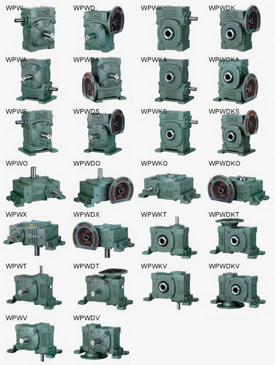
The WPWS maintains all the installation advantages of the WPW platform — integral flanged base, five mounting orientations, multi-face oil ports — while adding the thermal resilience needed for cement plant conveyor drives, mining equipment auxiliaries, and outdoor industrial equipment in hot climate regions. Available in 12 sizes (40–250 mm), ratios 1/5–1/60. O Ever-power | Request Thermal Assessment
Technical Specifications
WPWS shares base and output dimensions with WPWA (shared specification drawing). HL = housing height including fin array; larger than WPW smooth-body equivalent. All dimensions in mm; reference input speed 1500 r/min.

| Size | Ratio | A | AB | B | BB | AC | BC | CC | HL | LL | H | M | N | E | F | G | Z | HS | U | T×V | LS | S | W×Y | Wt(kg) | |
|---|---|---|---|---|---|---|---|---|---|---|---|---|---|---|---|---|---|---|---|---|---|---|---|---|---|
| 40 | 1/5–1/60 | 143 | 87 | 114 | 74 | 95 | 61 | 40 | 45 | 60 | 135 | 100 | 130 | 80 | 110 | 10 | 10 | 25 | 12 | 4×2.5 | 28 | 14 | 5×3 | 5 | |
| 50 | 175 | 108 | 150 | 97 | 111 | 68 | 60 | 80 | 93 | 195 | 130 | 150 | 100 | 105 | 120 | 18 | 12 | 40 | 15 | 5×3 | 50 | 22 | 7×4 | 8 | |
| 60 | 198 | 120 | 168 | 112 | 127 | 76 | 60 | 80 | 93 | 195 | 130 | 150 | 100 | 105 | 120 | 18 | 12 | 40 | 15 | 5×3 | 50 | 22 | 7×4 | 12 | |
| 70 | 231 | 140 | 194 | 131 | 152 | 86 | 70 | 73 | 108 | 233 | 150 | 190 | 115 | 150 | 18 | 15 | 50 | 18 | 5×3 | 60 | 28 | 7×4 | 16 | ||
| 80 | 261 | 160 | 214 | 142 | 169 | 102 | 80 | 83 | 123 | 268 | 170 | 220 | 135 | 180 | 18 | 15 | 50 | 22 | 7×4 | 65 | 32 | 10×4.5 | 25 | ||
| 100 | 322 | 190 | 254 | 169 | 216 | 117 | 100 | 100 | 150 | 330 | 190 | 270 | 155 | 220 | 20 | 15 | 50 | 25 | 7×4 | 75 | 38 | 10×4.5 | 40 | ||
| 120 | 371 | 219 | 282 | 190 | 256 | 124 | 120 | 120 | 180 | 395 | 230 | 320 | 180 | 260 | 25 | 18 | 65 | 30 | 7×4 | 85 | 45 | 12×4.5 | 58 | ||
| 135 | 422 | 249 | 317 | 210 | 296 | 147 | 135 | 135 | 215 | 450 | 250 | 350 | 200 | 290 | 30 | 18 | 75 | 35 | 10×4.5 | 95 | 55 | 16×6 | 86 | ||
| 155 | 497 | 295 | 382 | 252 | 345 | 185 | 155 | 135 | 235 | 493 | 280 | 380 | 220 | 320 | 32 | 21 | 85 | 40 | 12×5 | 110 | 60 | 18×7 | 112 | ||
| 175 | 534 | 314 | 373 | 255 | 374 | 192 | 175 | 160 | 260 | 558 | 310 | 410 | 250 | 350 | 37 | 21 | 85 | 45 | 14×5.5 | 110 | 65 | 18×7 | 154 | ||
| 200 | 580 | 342 | 456 | 319 | 412 | 230 | 200 | 175 | 290 | 620 | 355 | 445 | 290 | 390 | 45 | 24 | 95 | 50 | 14×5.5 | 125 | 70 | 20×7.5 | 218 | ||
| 250 | 705 | 420 | 552 | 385 | 500 | 285 | 250 | 200 | 350 | 750 | 460 | 560 | 380 | 480 | 50 | 28 | 110 | 60 | 18×7 | 155 | 90 | 25×9 | 353 |
* WPWS and WPWA share the specification drawing. HL = height including fin array — greater than WPW equivalent. All flanged base dimensions (AC, BC, CC) and shaft dimensions identical to WPW. Direct thermal upgrade with HL clearance verification.
Product Structure — Universal Housing with Cast-Integral Fin Array
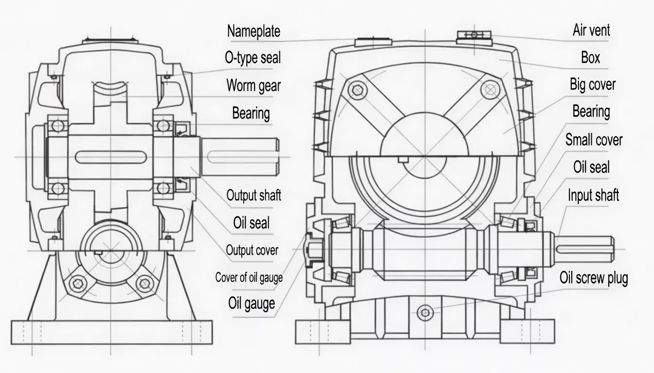
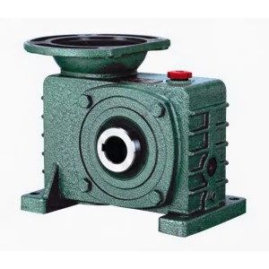
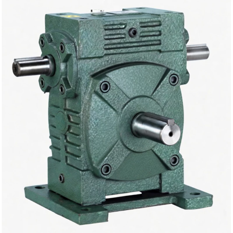
The WPWS extends the WPW flanged-base housing with cast-integral longitudinal cooling fins on the housing top and outer side faces. The fins are part of the same foundry casting as the housing body — permanent, with no risk of loosening or separation under the vibration and thermal cycling of industrial environments. The flanged base, multi-face oil ports, and precision worm gear internals are unchanged from the WPW.
| Cooling Fins | Cast-integral longitudinal fins; ~15°C lower vs WPW at rated load |
| Orientations | 5 positions (A–E); fin array positioned for maximum natural convection in each |
| Base | Integral flanged base; 4 anchor bolt positions; same dims as WPW |
| Oil System | Multi-face ports for all 5 positions; same as WPW platform |
| Upgrade Path | Direct thermal upgrade from WPW — same base dims; verify HL clearance |
| Housing | FC25 cast iron; all fins cast as part of housing body |
✅ Key Features & Benefits
~15°C Lower Temperature for Continuous Heavy-Duty Service
The WPWS fin array maintains oil sump temperature approximately 15°C lower than the WPW smooth-body at rated load. In cement plants, outdoor mining equipment, and tropical industrial environments where ambient temperatures reach 40–45°C, this margin is often the difference between stable continuous operation and recurring overtemperature stops. Keywords: universal worm reducer cooling fins, thermal stability flanged-base worm gearbox.
Permanent Fins for Industrial Environments
The cast-integral fins cannot loosen, corrode away, or separate under the vibration and thermal cycling of cement plants, mining sites, and heavy outdoor equipment. Unlike bolt-on thermal accessories, the WPWS thermal performance is consistent throughout the entire service life with no maintenance required for the fin system.
Full Universal Platform — All Five Orientations
The WPWS retains all five mounting orientations of the WPW platform. The fin array is positioned to maximise natural convection in the most common (horizontal) orientation, with adequate performance in all other rated positions. Correct fin orientation relative to air flow direction should be confirmed for each installation — contact us for guidance.
Extended Lubricant Life in Continuous Applications
Reducing oil sump temperature by 15°C approximately doubles lubricant oxidation life. In continuous industrial applications (cement kilns, mining conveyors, chemical plant drives) the WPWS can extend drain intervals from the standard 2,500 hours to 3,500–4,500+ hours, reducing maintenance stops and lubricant consumption.
Direct Thermal Upgrade from WPW
The WPWS base footprint (A, AB, B, BB, AC, BC, CC dimensions) and shaft dimensions are identical to the WPW. Where an installed WPW is experiencing overtemperature issues, the WPWS is the minimum-disruption upgrade — verify HL height clearance and swap in place.
Same Precision Gearing — No Performance Trade-Off
The WPWS uses the same 20CrMnTi worm and ZCuSn10Pb1 bronze wheel pair as the WPW. The fins add thermal performance without any change to gear mesh geometry, transmission efficiency, noise level, or output torque capacity.
Industry Applications
The WPWS is specified wherever universal multi-orientation mounting must be combined with sustained thermal stability under continuous industrial loads:
Cement PlantsClinker conveyor auxiliary drives, raw mill feeder drives, and cement plant conveyor systems in hot enclosed plant rooms where ambient temperatures regularly exceed 40°C and continuous duty is required.
Mining EquipmentSurface mine conveyor auxiliary drives, underground mine ventilation fan drives, and mineral processing plant conveyor systems in hot climate mining regions requiring thermally stable universal-mount drives.
Outdoor Hot-Climate IndustryAny outdoor industrial conveyor drive in Gulf region, South Asian, or tropical environments where the combination of solar loading and ambient temperature creates severe thermal conditions for enclosed gearboxes.
Chemical & Process IndustryContinuous chemical process conveyor drives, reactor feed conveyor systems, and chemical plant auxiliary drives requiring thermally stable universal-mount gearboxes for 24/7 operation in warm enclosed plant rooms.
Biomass & EnergyBiomass conveyor drives, wood chip handling system drives, and bioenergy plant auxiliary conveyor systems operating in warm, dusty outdoor environments requiring both universal mounting and thermal stability.
Glass & CeramicsGlass batch conveyor drives, ceramic kiln conveyor auxiliaries, and refractory material handling systems where hot plant room environments combined with continuous duty require the WPWS’s thermal advantage over the standard WPW.
Quality Control & Certification
ISO 9001:2015 & CE
Full ISO 9001:2015 QMS. CE Declaration of Conformity per shipment. Fin casting quality verified at foundry stage for completeness and geometry. SGS/BV inspection available for cement and mining industry compliance documentation.
️ Thermal Stability Run Test
Each WPWS undergoes a 60-minute thermal stability run at 110% rated torque with oil sump temperature measured at stabilisation. Temperature must remain below 90°C — providing 5°C safety margin below the 95°C maximum. This test confirms the fin array is delivering its rated thermal benefit on every unit before shipment.
Material Standards
Housing and fins: FC25 cast iron (≥250 MPa). Worm: 20CrMnTi (≥58 HRC). Wheel: ZCuSn10Pb1 tin-bronze. Third-party inspection for mining and cement sector procurement compliance on request.
Why Choose Ever-power for WPWS Gearboxes
We supply WPWS thermally optimised universal gearboxes to cement plant equipment builders, mining equipment OEMs, and chemical process machinery manufacturers in Korea, India, the UK, Australia, and over 60 countries worldwide. Our 60-minute thermal stability run test — with pass criterion set to 90°C, not just the 95°C maximum — is the quality assurance standard that cement and mining customers rely on for reliable performance in their most thermally demanding applications.
- ✅ 60-min thermal run test at 110% torque — pass ≤90°C, every unit
- ✅ Foundry-stage fin geometry inspection before machining
- ✅ Cement & mining sector documentation packages on request
- ✅ Thermal simulation service — model your ambient and duty cycle
- ✅ 20+ years export record — Korea, India, UK, Australia and beyond
⭐ Customer Reviews
“We upgraded our clinker conveyor drives from WPW to WPWS after recurring overtemperature trips during our summer production season. The difference is exactly as described — the units run approximately 14°C cooler on the same duty cycle. We’ve extended our oil change interval by 40% and had zero thermal trips in 16 months since the upgrade. The flanged base mounting was straightforward.”
Sean M., Maintenance Engineer
Cement Plant, South Australia, Australia
“We specify WPWS for all our mining conveyor auxiliary drives destined for Southeast Asian and Middle Eastern markets. The fin cooling provides the thermal headroom needed for 45°C+ outdoor ambient temperatures that our customers experience in summer. The flanged base universal mounting simplifies our installation at various conveyor angles. Consistent quality from Ever-power.”
Min-jun L., Senior Engineer
Mining Equipment OEM, Incheon, South Korea
“We use WPWS on our continuous chemical process conveyor drives. Our plant rooms reach 43°C in summer and our drives run 24/7. The thermal stability of the WPWS in these conditions is significantly better than the standard WPW units we used previously. Extended lubricant intervals are a measurable cost saving across our fleet of 30+ units.”
Rajan P., Drive Systems Engineer
Chemical Process Plant, Gujarat, India
“WPWS units on our glass batch conveyor drives in a very warm plant room environment. The finned housings handle our plant room temperatures without issues. The universal flanged base fits our conveyor structure angles perfectly. One batch had a slight dimensional query that Ever-power resolved promptly. Would recommend for hot industrial environments.”
David H., Plant Engineer
Glass Manufacturing, Birmingham, United Kingdom
❓ Frequently Asked Questions
What is the difference between WPWS and WPW?
The WPW has a smooth-body housing. The WPWS has identical flanged base, shaft, and gear dimensions but adds cast-integral cooling fins that reduce sustained oil temperature by approximately 15°C at rated load. All installation dimensions, anchor bolt specifications, and shaft dimensions are identical — the WPWS is a direct thermal upgrade for the WPW with HL height clearance verification.
How much cooler does the WPWS run compared to the WPW?
At rated load and 40°C ambient, the WPWS typically maintains oil sump temperature approximately 13–16°C lower than an equivalent WPW. At 45°C ambient, this differential may reach 18°C. The exact differential depends on load, duty cycle, and air circulation around the fin array. Contact us with your operating conditions for a specific thermal calculation.
Does the fin array require maintenance?
No regular maintenance is required for the fin array — the fins are cast as part of the housing and cannot loosen. In dusty environments (cement plants, mining), inspect the fin channels annually and clean with compressed air if significant accumulation is visible. Blocked fin channels reduce thermal performance. In outdoor installations, ensure fins are oriented to allow natural air circulation rather than being enclosed by machine guarding.
What is the maximum ambient temperature for WPWS continuous operation?
With standard ISO VG 320 mineral oil, the WPWS can typically operate at rated load continuously in ambient temperatures up to approximately 43–45°C without exceeding the 95°C maximum sump temperature (subject to load, duty cycle, and air circulation). With synthetic PG ISO VG 460 oil, this extends to approximately 48–50°C. Contact us for a precise calculation for your specific conditions.
Can I use the WPWS at all five mounting orientations?
Yes — the WPWS supports all five standard WPW mounting orientations (A–E). The fin array position is fixed on the housing body; in vertical mounting orientations, the fin array may be on the housing side rather than the top face, which slightly reduces natural convection effectiveness. For continuous duty in vertical orientation at high ambient temperatures, contact us for a position-specific thermal assessment.
Universal Mounting + Thermal Stability — Get WPWS Quote
If your cement plant, mining, or outdoor industrial drive needs universal mounting flexibility AND reliable thermal performance in hot conditions, the WPWS delivers both. Our engineers will calculate the thermal margin for your specific ambient and duty cycle.