描述
WPEDS Flange-Mounted Double Speed Worm Gear Reducer with Cooling Fins — The Complete Thermal Solution for Motor-Direct Two-Stage Continuous Industrial Drives
A motor-direct two-stage worm gearbox operating at 1/600–1/900 ratio in a chemical plant, rubber factory, or continuous process line presents the ultimate thermal challenge: motor heat and two gear-mesh heat loads are all generated simultaneously in a compact enclosed assembly. The WPEDS flange-mounted double speed worm gear reducer with cooling fins is the purpose-designed answer — combining IEC motor direct mounting, two-stage ultra-high ratio reduction, and an integral cooling fin array in a single cast iron unit.
The WPEDS maintains oil sump temperatures approximately 18°C lower than the equivalent smooth-body WPEDA at rated load — the most critical thermal margin available for rubber, plastics, and continuous chemical process industries where an overtemperature stop costs thousands in batch losses. Available in 9 size groups, motors 0.12–5.5 kW, ratios 1/200–1/900. 关于永恒之力 | Request Thermal Assessment
Technical Specifications
WPEDS shares the WPEDA base footprint with increased HL due to integral fins. Motor flange: LA, LB, LC, LE, LZ per IEC 60034-7. Input hole: Q, U, T×V. Output: LS, S, W×Y. Reference speed 1500 r/min. All dimensions in mm.
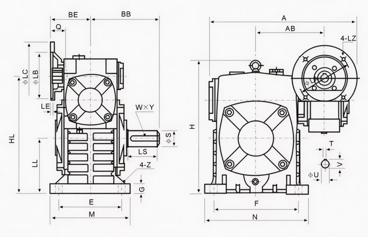
| Size | Power(kW) | Ratio | A | AB | BB | BE | HL | LL | H | M | N | E | F | G | Z | LA | LB | LC | LE | LZ | Q | U | T×V | LS | S | W×Y | Wt(kg) |
|---|---|---|---|---|---|---|---|---|---|---|---|---|---|---|---|---|---|---|---|---|---|---|---|---|---|---|---|
| 40-70 | 0.12 | 1/200–1/900 | 314 | 153 | 131 | 75 | 215 | 105 | 238 | 150 | 190 | 115 | 150 | 20 | 15 | 115 | 95 | 140 | 4 | M8 | 31 | 11 | 4×12.8 | 60 | 28 | 7×4 | 19 |
| 50-80 | 0.18 | 314 | 144 | 142 | 83 | 130 | 160 | 268 | 170 | 220 | 135 | 180 | 20 | 15 | 115 | 95 | 140 | 4 | M8 | 31 | 14 | 4×12.8 | 65 | 32 | 10×4.5 | 27 | |
| 60-100 | 0.37 | 1/200 | 387 | 175 | 169 | 91 | 310 | 150 | 334 | 190 | 270 | 155 | 220 | 25 | 15 | 130 | 110 | 160 | 4 | M8 | 33 | 14 | 5×16.3 | 75 | 38 | 10×4.5 | 45 |
| 70-120 | 0.37/0.75 | 1/300–1/400 | 445/425 | 193 | 190 | 109/111 | 370 | 180 | 423 | 230 | 320 | 180 | 260 | 30 | 18 | 130/165 | 110/130 | 160/200 | 4 | M8/M10 | 40/42 | 14/19 | 5×16.3/6×21.8 | 85 | 45 | 12×4.5 | 75 |
| 80-135 | 0.75/1.5 | 1/500–1/600 | 499 | 226 | 210 | 125 | 430 | 215 | 482 | 250 | 350 | 200 | 290 | 30 | 18 | 165 | 130 | 200 | 4.5 | M10 | 48/52 | 19/24 | 6×21.8/8×27.3 | 95 | 55 | 16×6 | 103 |
| 100-155 | 1.5 | 1/800 | 570 | 269 | 252 | 148 | 490 | 235 | 541 | 275 | 390 | 220 | 320 | 35 | 21 | 165 | 130 | 200 | 4.5 | M10 | 52 | 24 | 8×27.3 | 110 | 60 | 18×7 | 147 |
| 120-175 | 2.2/3.0 | 1/900 | 631 | 287 | 255 | 181 | 555 | 260 | 600 | 310 | 430 | 250 | 350 | 40 | 21 | 215 | 180 | 250 | 5 | M12 | 63 | 28 | 8×31.3 | 110 | 65 | 18×7 | 204 |
| 135-200 | 3.0/4.0 | 580 | 318 | 319 | 202 | 625 | 290 | 677 | 360 | 480 | 290 | 390 | 40 | 24 | 215 | 180 | 250 | 5 | M12 | 63 | 28 | 8×31.3 | 125 | 70 | 20×7.5 | 298 | |
| 155-250 | 5.5 | 815 | 380 | 385 | 247 | 755 | 350 | 824 | 460 | 560 | 380 | 480 | 45 | 28 | 265 | 230 | 300 | 5 | M12 | 83 | 38 | 10×41.3 | 155 | 90 | 25×9 | 470 |
* HL = total housing height including fin array. WPEDS and WPEDA share identical base footprint, flange dimensions, and shaft dimensions — WPEDS is a direct thermal upgrade for existing WPEDA installations where adequate vertical clearance exists.
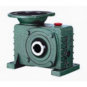
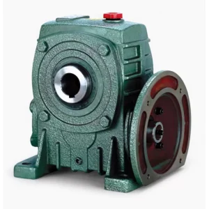
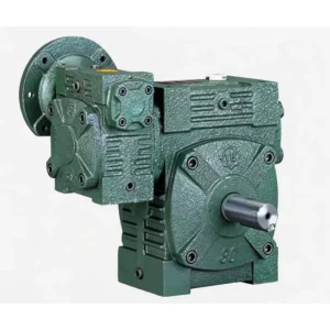
Product Structure — Triple-Feature Two-Stage Design
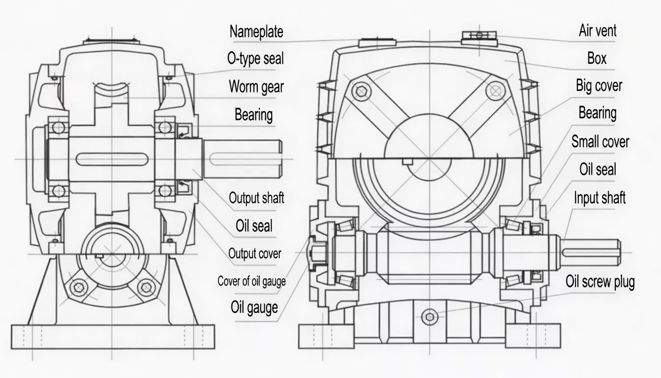
The WPEDS integrates three features in a single FC25 cast iron two-stage housing: an IEC motor flange at the input, two serial worm-and-wheel stages delivering 1/200–1/900 combined ratio, and cast-integral longitudinal cooling fins on the top and side faces. All three features are part of the single casting — no bolt-on accessories, no secondary bonding, no vibration risk at any component interface.
| Feature 1 | IEC 60034-7 motor flange — motor shaft direct, no input coupling |
| Feature 2 | Two worm-and-wheel stages in series — ratio 1/200–1/900 |
| Feature 3 | Cast-integral fins — ~18°C lower sustained temperature vs WPEDA |
| Thermal Benefit | Manages heat from motor + two gear stages simultaneously |
| Housing | FC25 cast iron; all three features integral — same footprint as WPEDA |
| Output | Solid shaft with keyway; 5 direction positions (A–E) |
✅ Key Features & Benefits
Three Heat Sources — One Thermal Solution
A motor-direct two-stage drive generates heat from three simultaneous sources: the motor winding, the first-stage gear mesh, and the second-stage gear mesh. The WPEDS fin array is sized to manage all three heat contributions together, maintaining stable oil sump temperature at rated load and up to 45°C ambient without supplemental cooling. Keywords: motor-direct finned two-stage worm gearbox, thermal double speed reducer.
~18°C Lower Temperature vs WPEDA
At rated load and 40°C ambient, the WPEDS maintains oil sump temperature approximately 18°C lower than the smooth-body WPEDA. In rubber vulcanisation and plastics processing environments where ambient temperatures regularly reach 45°C+, this margin keeps the WPEDS safely below the 95°C oil temperature limit where the WPEDA may reach it under full load.
IEC Flange for Rapid Motor Swap
The IEC 60034-7 pilot register allows motor replacement in 15–20 minutes in rubber and plastics plant environments where emergency motor changes during production runs must be completed without batch loss. No coupling to remove, no alignment to re-check — motor slides out, new motor slides in.
Cast-Integral Fins — Permanent Thermal Performance
Fins are integral to the housing casting, ensuring permanent thermal performance with no risk of fin separation under the vibration and thermal cycling characteristic of rubber vulcanisation and plastics processing environments. Unlike bolt-on thermal accessories, the WPEDS fin performance cannot degrade.
Drop-In Thermal Upgrade from WPEDA
WPEDS shares the identical base footprint, flange dimensions, and shaft dimensions with WPEDA. For any WPEDA installation experiencing overtemperature issues in hot process environments, the WPEDS is the minimum-disruption thermal upgrade — verify HL height clearance and swap in place.
VSD/Inverter Compatible — Thermal Headroom for Low-Speed Operation
At low VSD frequencies (20–35 Hz), TEFC motor cooling reduces while the two-stage gear heat generation continues at full load level — increasing the thermal burden on the gearbox. The WPEDS fin array provides additional thermal headroom for these demanding low-speed VSD operation conditions.
Industry Applications
The WPEDS is the premier solution when motor-direct two-stage ultra-high ratio drive must perform reliably at high duty cycles in thermally demanding environments:
Rubber & Vulcanisation IndustryRubber vulcanisation line transport drives, rubber compounding mill auxiliary drives, and tyre building machine slow-speed drives where combined motor and two-stage gearbox heat generation in enclosed plant rooms demands thermal management.
Plastics & Polymer ProcessingPlastic film line auxiliary drives, polymer blending vessel agitators, and continuous extruder accessory drives operating at very low speeds in warm, enclosed factory environments.
Chemical Process — Continuous OperationContinuous chemical reactor agitator drives operating at 90%+ duty cycle, polymerisation vessel drives, and specialty adhesive manufacturing vessel drives requiring ultra-low speed motor-direct two-stage drive with thermal stability.
Bioprocessing & FermentationLarge bioreactor and fermentation vessel agitator drives requiring very low impeller speeds, compact motor-direct mounting, and reliable thermal performance during extended 24/7 batch production cycles.
Hot Climate Continuous DrivesAny outdoor or poorly-ventilated industrial drive in tropical, subtropical, or Gulf region environments where ambient temperatures regularly exceed 40°C and the combined thermal load of motor and two-stage gearbox requires fin-assisted dissipation.
Battery & New Energy ManufacturingElectrode slurry mixing vessel drives, battery electrolyte agitation systems, and new energy material processing equipment requiring compact motor-direct ultra-low-speed drives with thermal stability.
Quality Control & Certification
ISO 9001:2015 & CE
Full ISO 9001:2015 QMS. CE Declaration of Conformity per shipment. Fin casting quality inspected at foundry stage before machining commences — fin completeness, wall thickness, and geometry verified against drawing spec.
️ Triple-Source Thermal Run Test
Each WPEDS undergoes a 90-minute thermal stability run at 110% rated torque. Oil sump temperature must stabilise below 95°C, with temperature differential between the two stage positions ≤10°C. This test validates that the fin array manages the combined three-source heat load under the most demanding rated conditions.
Material & Fin Verification
Housing: FC25 cast iron (≥250 MPa). Both worm shafts: 20CrMnTi (≥58 HRC). Wheel rims: ZCuSn10Pb1. IEC flange CMM verified (≤0.05 mm TIR). Fin geometry verified at casting stage. Third-party SGS/BV inspection available for rubber, plastics, and chemical industry quality audits.
Why Choose Ever-power for WPEDS Gearboxes
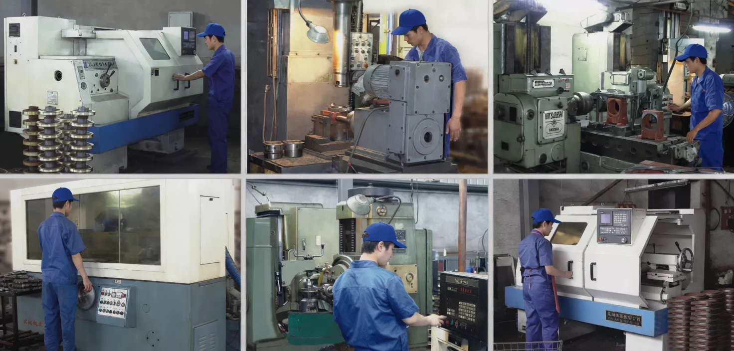
We supply WPEDS triple-feature gearboxes to rubber industry equipment builders, plastics processing machinery manufacturers, and continuous chemical process OEMs in the USA, Spain, South Africa, Australia, and over 60 countries. Our 90-minute thermal stability test at 110% rated torque is a higher standard than our WPEDA test — because the WPEDS customer is one who genuinely cannot afford an overtemperature failure in their production environment.
- ✅ 90-minute thermal stability test at 110% rated torque — every unit
- ✅ Foundry-stage fin geometry inspection — before machining
- ✅ IEC flange CMM + two-stage mesh + thermal verification — triple check
- ✅ Thermal simulation service — model your three-source heat load before ordering
- ✅ 20+ years export record — USA, Spain, South Africa, Australia and beyond
⭐ Customer Reviews
“We upgraded our vulcanisation line transport drives from WPEDA to WPEDS after repeated overtemperature trips during summer production in our enclosed plant room. The improvement is dramatic — the WPEDS units run 17°C cooler on the same duty cycle and we have had zero thermal stops in 15 months since the upgrade. The three-feature combination is exactly what our application needed.”
Chris B., Production Engineer
Rubber Products Plant, New South Wales, Australia
“We specify WPEDS for all motor-direct two-stage drives on our plastic film line equipment. The three features — IEC flange, 1/600 ratio, cooling fins — are all required for our application. Build quality from Ever-power is excellent and the thermal performance consistently meets our specification. We have ordered eight batches now with zero quality rejections.”
Michael C., Drive Systems Engineer
Plastics Processing OEM, Ohio, USA
“Our continuous chemical agitator drives run 24/7 in enclosed plant rooms at 42°C ambient. The WPEDS units manage the combined motor and two-stage gear heat load without supplemental cooling — impossible with the smooth-body WPEDA we used previously. The 1/800 ratio achieves the very slow impeller speeds our process requires. Excellent product.”
Carlos R., Maintenance Manager
Chemical Process Plant, Barcelona, Spain
“WPEDS on our rubber compound mixer drives in a hot plant room. The combined fins handle our summer ambient temperatures (up to 44°C) well. The IEC flange makes motor maintenance easier. One batch had slightly longer delivery than stated but Ever-power communicated proactively. Overall very satisfied with the product.”
Thabo M., Process Engineer
Rubber Compounding Plant, Johannesburg, South Africa
❓ Frequently Asked Questions
What is the difference between WPEDS and WPEDA?
The WPEDA has an IEC motor flange and two-stage worm drive in a smooth-body housing. The WPEDS has the same motor flange and two-stage drive but adds integral cooling fins that reduce sustained oil temperature by ~18°C. All flange, bore, and base footprint dimensions are identical. Choose WPEDA for standard duty; choose WPEDS for high-duty-cycle or hot-ambient applications where the combined motor and two-stage heat generation exceeds the smooth-body WPEDA’s thermal capacity.
How much hotter does a two-stage motor-direct drive run compared to a single-stage?
A motor-direct two-stage drive generates heat from three sources simultaneously: motor winding, first-stage worm mesh, and second-stage worm mesh. In practice, a WPEDA in a 40°C plant room may reach 88–92°C oil sump temperature at rated load — close to the 95°C limit. The WPEDS reduces this to 70–75°C — comfortable headroom even at 45°C ambient. For rubber and plastics applications running 16+ hours per day, this thermal margin is the primary reason for specifying WPEDS over WPEDA.
Can I replace a WPEDA with a WPEDS without machine modification?
Yes, in most cases. The WPEDS shares the identical base footprint, IEC flange dimensions, and shaft dimensions with the WPEDA for each size group. The only dimensional difference is the increased housing height (HL) due to the fin array. Verify that available vertical clearance above your existing WPEDA exceeds the WPEDS HL value for your size group. If clearance is sufficient, it is a direct swap.
What synthetic lubricant extends WPEDS thermal performance further?
For ambient temperatures above 40°C or applications where oil sump temperatures may approach 80°C even with the WPEDS fins, we recommend upgrading from ISO VG 320 mineral oil to synthetic PAG ISO VG 460. PAG oils offer substantially higher thermal stability, lower friction coefficients (reducing gear heat generation as well as managing it), and drain intervals of 5,000+ hours in many applications — providing a further thermal margin on top of the fin-array benefit.
Does the WPEDS require any special maintenance for the fin array?
For standard industrial environments, no special fin maintenance is required. In dusty environments (rubber powder, plastic dust, chemical particulate), inspect fin channels annually and clean with compressed air if accumulation is visible. In WPEDS applications where VSD operation at low speeds is used, ensure adequate plant ventilation or air circulation around the fin array — natural convection is less effective when the unit is stationary or running very slowly.
The Complete Thermal Solution for Motor-Direct Two-Stage Drives
If your motor-direct two-stage drive is approaching thermal limits in a hot or continuous-duty environment, the WPEDS delivers the integrated solution. Our engineers will model your three-source heat load and confirm the correct specification.