描述
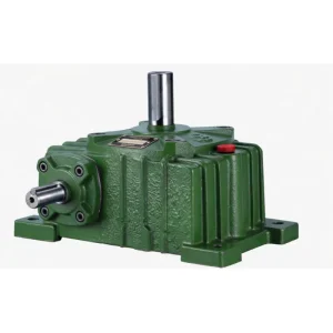
WPDA Flange-Mounted Single Speed Worm Gear Reducer — Motor-Direct Integration for Compact, Zero-Backlash Drive Systems
Every additional component between a motor and its load introduces potential misalignment, backlash, and maintenance burden. The WPDA flange-mounted worm gear reducer eliminates these intermediaries entirely by incorporating an integral motor flange that accepts IEC/NEMA standard motors directly — creating a compact, precisely aligned motor-gearbox unit without the need for couplings, spacers, or a separate motor baseplate. The result is a tighter transmission chain, lower vibration, reduced overall machine footprint, and significantly simplified installation.
The WPDA accepts motors from 0.12 kW to 15 kW across 13 frame sizes (40–250 mm) and supports all standard ratios from 1/5 to 1/60. Its FC25 cast iron housing delivers the same heavy-duty performance as the WPA footprint series, while the IEC flange connection ensures universal motor compatibility. This is the motor-direct worm gearbox of choice for food processing machinery, packaging lines, and any application where machine build quality demands clean, compact drive integration. 关于永恒之力 | Request a Quote
Technical Specifications
Full dimensional and motor flange data for all WPDA sizes. Input reference speed: 1500 r/min. Flange data: LA=flange OD; LB=pilot diameter; LC=bolt circle; LE=bolt count; LZ=bolt size. Input hole: Q=bore; U=depth; T×V=keyway. All dimensions in mm.
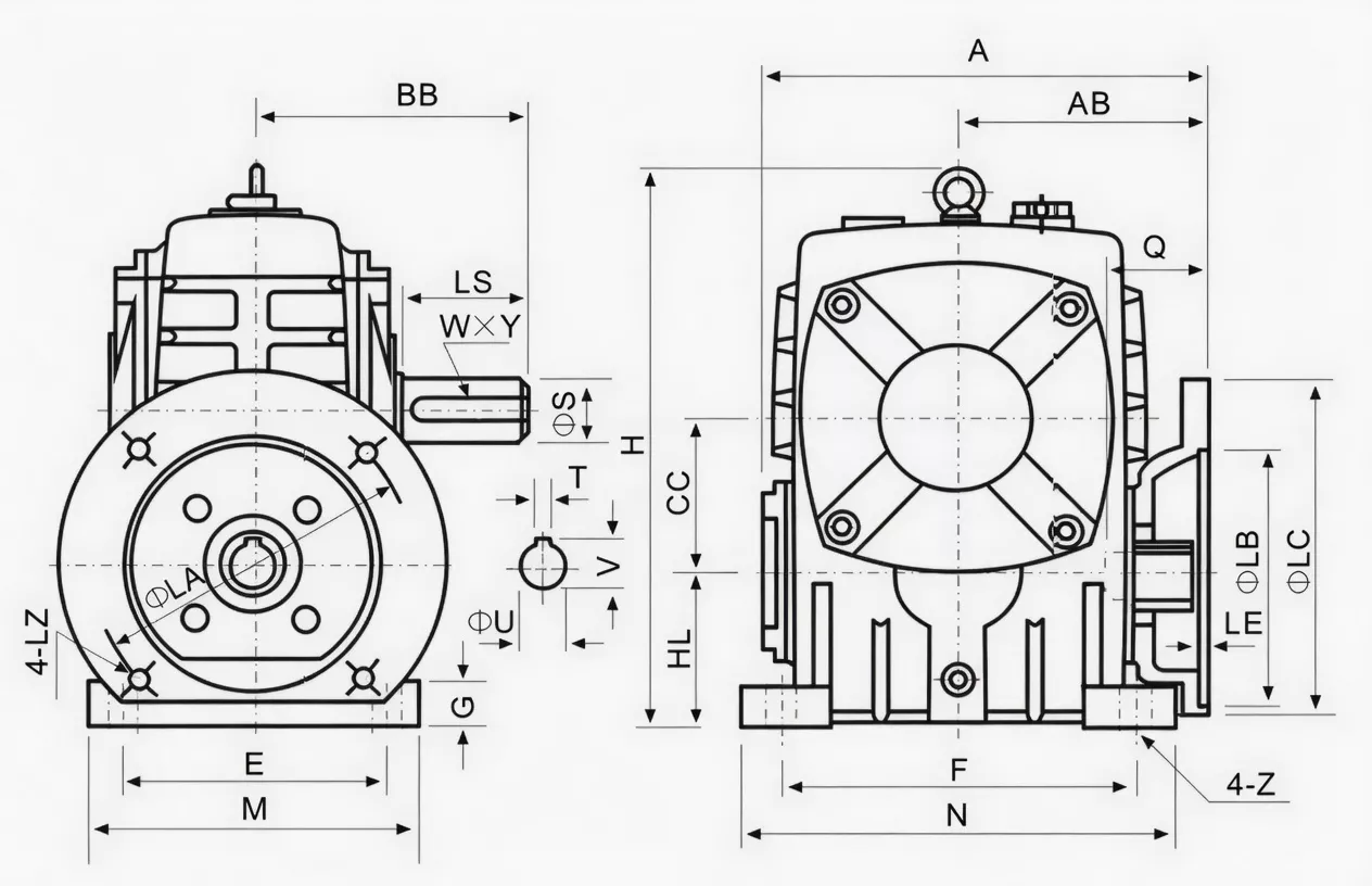
| Size | Power(kW) | Ratio | A | AB | BB | CC | H | HL | M | N | E | F | G | Z | LA | LB | LC | LE | LZ | Q | U | T×V | LS | S | W×Y | Wt(kg) |
|---|---|---|---|---|---|---|---|---|---|---|---|---|---|---|---|---|---|---|---|---|---|---|---|---|---|---|
| 40 | 0.12 | 1/5–1/60 | 135 | 75 | 74 | 40 | 138 | 40 | 90 | 100 | 70 | 80 | 13 | 10 | 115 | 95 | 140 | 4 | M8 | 31 | 11 | 4×12.8 | 28 | 14 | 5×3 | 5 |
| 50 | 0.18 | 151 | 83 | 97 | 50 | 176 | 50 | 120 | 140 | 95 | 110 | 15 | 12 | 115 | 95 | 140 | 4 | M8 | 31 | 11 | 4×12.8 | 40 | 17 | 5×3 | 8 | |
| 60 | 0.37 | 167 | 91 | 112 | 60 | 204 | 60 | 130 | 150 | 105 | 120 | 20 | 12 | 130 | 110 | 160 | 4 | M8 | 33 | 14 | 5×16.3 | 50 | 22 | 7×4 | 11 | |
| 70 | 0.37/0.75 | 200/202 | 109/111 | 131 | 70 | 236 | 70 | 150 | 190 | 115 | 150 | 20 | 15 | 130/165 | 110/130 | 160/200 | 4 | M8/M10 | 40/42 | 14/19 | 5×16.3/6×21.8 | 60 | 28 | 7×4 | 17 | |
| 80 | 0.75/1.5 | 225 | 125 | 142 | 80 | 268 | 80 | 170 | 220 | 135 | 180 | 20 | 15 | 165 | 130 | 200 | 4.5 | M10 | 48/52 | 19/24 | 6×21.8/8×27.3 | 65 | 32 | 10×4.5 | 22 | |
| 100 | 1.5/2.2/3.0 | 280 | 148 | 169 | 100 | 336 | 100 | 190 | 270 | 155 | 220 | 25 | 15 | 165 | 130 | 200 | 4.5 | M10 | 52 | 24 | 8×27.3 | 75 | 38 | 10×4.5 | 38 | |
| 120 | 2.2/3.0 | 333 | 181 | 190 | 120 | 430 | 120 | 230 | 320 | 180 | 260 | 30 | 18 | 215 | 180 | 250 | 5 | M12 | 63 | 28 | 8×31.3 | 85 | 45 | 12×4.5 | 64 | |
| 135 | 3.0/4.0 | 375 | 202 | 210 | 135 | 480 | 135 | 250 | 350 | 200 | 290 | 30 | 18 | 215 | 180 | 250 | 5 | M12 | 63 | 28 | 8×31.3 | 95 | 55 | 16×6 | 85 | |
| 147 | 4.0 | 415 | 235 | 210 | 147 | 460 | 123 | 250 | 350 | 200 | 280 | 32 | 18 | 215 | 180 | 250 | 5 | M12 | 63 | 28 | 8×31.3 | 95 | 55 | 16×6 | 105 | |
| 155 | 5.5 | 448 | 247 | 252 | 155 | 531 | 135 | 275 | 390 | 220 | 320 | 35 | 21 | 265 | 230 | 300 | 5 | M12 | 83 | 38 | 10×41.3 | 110 | 60 | 18×7 | 118 | |
| 175 | 7.5 | 481 | 262 | 255 | 175 | 600 | 160 | 310 | 430 | 250 | 350 | 40 | 21 | 265 | 230 | 300 | 5 | M12 | 83 | 38 | 10×41.3 | 110 | 65 | 18×7 | 165 | |
| 200 | 11.0 | 543 | 285 | 319 | 200 | 666 | 175 | 360 | 480 | 290 | 390 | 40 | 24 | 300 | 250 | 350 | 6 | M16 | 114 | 42 | 12×45.3 | 125 | 70 | 20×7.5 | 236 | |
| 250 | 11.0/15.0 | 615 | 330 | 385 | 250 | 800 | 200 | 460 | 560 | 380 | 480 | 45 | 28 | 300 | 250 | 350 | 6 | M16 | 114 | 42 | 12×45.3 | 155 | 90 | 25×9 | 396 |
* Motor powers shown are representative matched motor sizes. Multiple motor sizes are separated by /. Flange dimensions comply with IEC 60034-7 standard motor mounting interfaces.
Product Structure — Integral Motor Flange Design
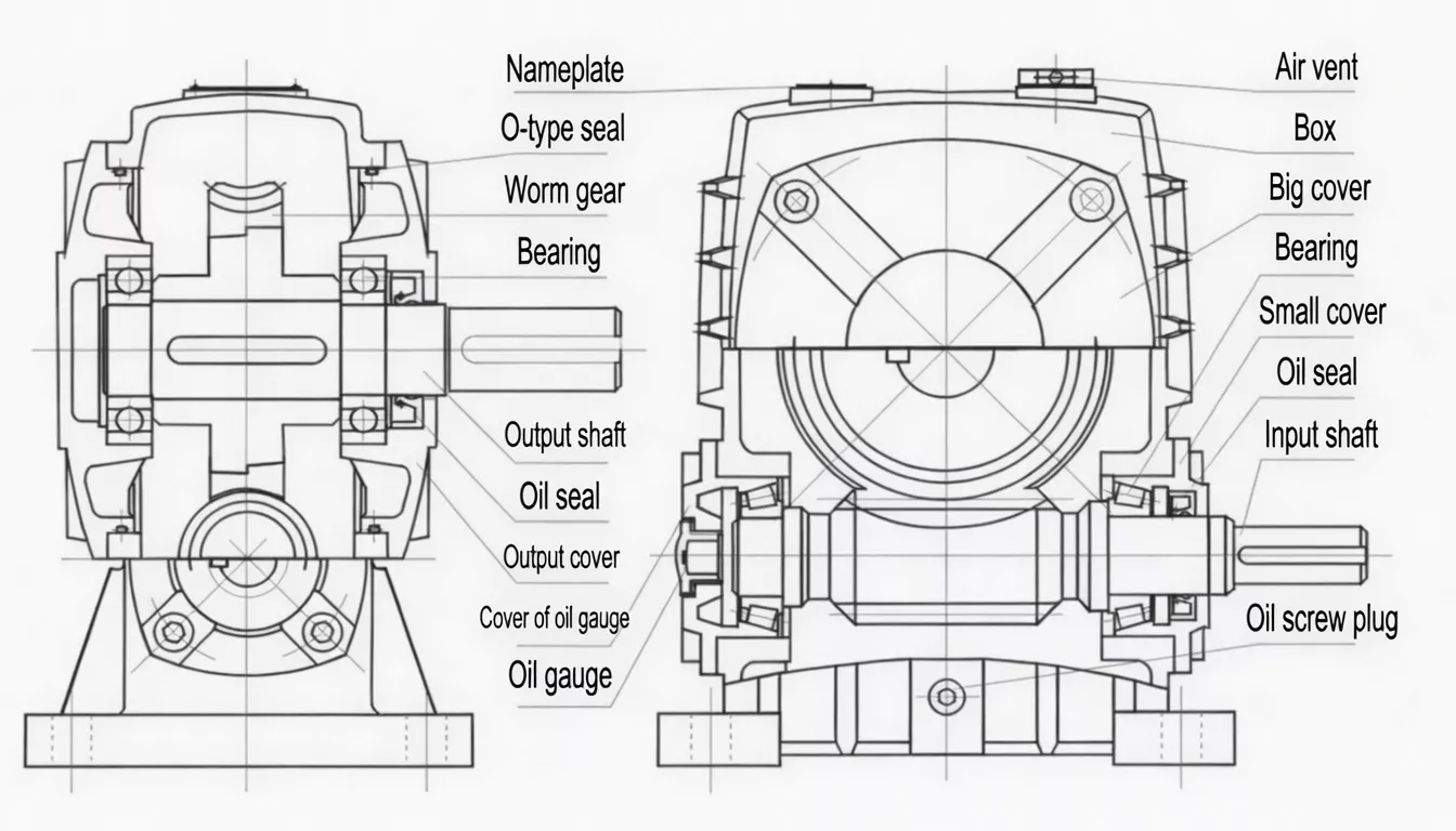
The WPDA housing features a rear-face IEC motor flange with a precision-bored pilot register that locates the motor shaft concentrically within the input bore to within 0.05 mm TIR. A broached input keyway transmits motor torque directly to the worm shaft without any intermediate coupling element, eliminating the coupling alignment step entirely from the installation procedure.
| Housing | FC25 grey cast iron, same footprint as WPA base series |
| Motor Flange | IEC 60034-7 standard dimensions; accepts single motor frame per size |
| Input Drive | Broached input bore with keyway — motor shaft inserts directly, no coupling |
| Worm Shaft | 20CrMnTi carburised & ground, ≥58 HRC; driven by motor shaft via key |
| Worm Wheel | ZCuSn10Pb1 tin-bronze rim on ductile iron hub |
| Output Shaft | Solid shaft with keyway; 5 direction positions (A–E) |
| Motor Compat. | Y/Y2 series (Chinese std.) and IE2/IE3 IEC motors; 0.12–15 kW |
✅ Key Features & Benefits
Direct Motor Integration — Zero Coupling
The IEC-compliant flange eliminates shaft couplings entirely. Motor-to-worm shaft connection is achieved by a direct keyed bore, cutting installation time from hours to minutes and permanently removing the coupling misalignment that is the leading cause of bearing and seal failure in indirect-drive gearboxes. Keywords: motor-direct worm gearbox, flange-mount worm reducer.
Precision Bore Alignment
The machined pilot register in the WPDA flange locates the motor frame to within 0.05 mm TIR, ensuring concentric motor shaft-to-worm axis alignment that minimises radial loads on the input bearings throughout the service life.
Rugged FC25 Cast Iron Housing
Identical material specification to the WPA series — FC25 grey cast iron providing outstanding impact resistance and vibration damping — ensures the WPDA delivers the same reliability in harsh industrial environments as the foot-mounted variants it is designed to replace.
Precision Worm & Wheel Pair
Ground 20CrMnTi worm and ZCuSn10Pb1 bronze wheel to ISO 1328 Grade 7 tolerances deliver smooth, quiet power transmission (≤72 dB(A)) with transmission efficiency of 60–90% depending on ratio. Keywords: precision worm gearbox for food processing.
Five Output Shaft Directions
Standard positions A through E allow the WPDA to integrate into any machine layout without angle-drive accessories, maintaining the installation flexibility of the foot-mounted WPA series within the compact motor-direct format.
Universal Motor Compatibility
WPDA flanges are dimensioned to IEC 60034-7 standards, accepting Y/Y2 series Chinese standard motors and IE2/IE3 efficiency class international motors. Matching motor power ratings from 0.12 kW (size 40) to 15 kW (size 250) span the full industrial drive spectrum.
Industry Applications
The WPDA motor-direct worm reducer is the preferred solution for compact machine design wherever an IEC motor is the prime mover:
Food Processing MachineryBread slicing lines, dough mixers, conveyor drives, and portioning machines where the compact motor-gearbox unit reduces machine width and simplifies CE machine safety compliance.
Packaging & Labelling LinesCarton erectors, case sealers, label applicators, and shrink-wrap lines requiring precise, compact, hygienic drive units with minimal grease or oil exposure risk.
Pharmaceutical ManufacturingTablet press auxiliaries, blister packaging drives, and clean-room conveyor systems where the WPDA’s compact, sealed configuration minimises contamination risk.
Paint & Coating LinesMixer drives, conveyor units, and automated surface treatment machinery benefiting from the WPDA’s compact footprint and vibration-free motor-direct drive.
FMCG & BeveragesFilling machines, capping lines, and labelling systems in fast-moving consumer goods production where quick motor swap-out during servicing is a maintenance advantage.
Light Industrial AutomationAssembly line conveyors, pick-and-place auxiliaries, and material handling systems in general automation requiring a small, clean, reliable gearbox-motor unit.
Quality Control & Certification
ISO 9001:2015 & CE
Full ISO 9001:2015 QMS. CE Declaration of Conformity per shipment. The WPDA’s IEC flange interface is dimensionally verified against IEC 60034-7 specifications at final inspection to ensure correct motor fit without shimming or modification.
Flange Concentricity & Run-Out Test
In addition to standard noise and leakage tests, each WPDA unit is checked for flange pilot concentricity (≤0.05 mm TIR) and input bore alignment relative to the output shaft centreline. This ensures the motor shaft enters the input bore without side load on the motor bearings.
Material Standards
Housing: FC25 cast iron (≥250 MPa). Worm: 20CrMnTi (≥58 HRC). Wheel rim: ZCuSn10Pb1 tin-bronze. Full material mill certificates provided on request for food-grade machine compliance documentation.
Why Choose Ever-power for WPDA Motor-Direct Gearboxes
We manufacture WPDA motor-direct gearboxes for food, packaging, and pharmaceutical OEMs across Japan, the Netherlands, Poland, Australia, and more than 60 countries worldwide. Our in-house flange machining and CMM inspection ensure every unit meets IEC 60034-7 dimensional compliance before shipment.
- ✅ IEC 60034-7 verified flange dimensions — CMM checked at final inspection
- ✅ OEM motor-matching service — we confirm motor frame compatibility before production
- ✅ Custom input bore options — special bore diameters and keyways for non-standard motors
- ✅ 20+ years export experience to food, pharma, and packaging industries globally
- ✅ Rapid delivery — WPDA stock held across key sizes; 7–15 working days standard
⭐ Customer Reviews
“We switched our entire mixing line from indirect-drive to WPDA motor-direct gearboxes. The installation time dropped from half a day per unit to under an hour. Zero coupling alignment issues since the changeover — a huge maintenance win for our customer.”
Sarah M., Production Engineer
Food Processing Line OEM, Victoria, Australia
“We use WPDA-80 and WPDA-100 units in our automated packaging lines. The IEC flange dimensions are exactly as specified — our standard motors fit without modification. Very consistent batch quality. Delivery to Japan is reliable and well-packaged.”
Hiroshi T., Mechanical Design Engineer
Packaging Machinery Builder, Osaka, Japan
“The WPDA series has become our standard specification for all conveyor drive heads up to 3 kW. The compact motor-gearbox assembly reduces our machine length by 120 mm per drive point — significant when you are building 40-metre sortation systems.”
Erik V., Technical Director
Conveyor Systems Manufacturer, Rotterdam, Netherlands
“Good quality WPDA gearboxes for our assembly line automation projects. The flange interface is accurate and our IE3 motors fit correctly every time. Slight variation in surface finish between batches, but dimensionally and functionally consistent. Would recommend.”
Tomasz K., Procurement Manager
Industrial Automation OEM, Wrocław, Poland
❓ Frequently Asked Questions
Which IEC motor frames are compatible with the WPDA flange?
Each WPDA size accepts a specific range of IEC frame motors. For example, size 80 accepts IEC frame 90 (flange LA=165 mm); size 100 accepts IEC frame 100/112; size 155 accepts IEC frame 160. The flange dimensions LA (outer diameter), LB (pilot diameter), LC (bolt circle), and LZ (bolt size) in the specification table correspond directly to IEC 60034-7 FF flange designations. Contact us with your motor frame number and we will confirm compatibility.
Can I fit a non-IEC motor (e.g., NEMA, Chinese Y-series) to the WPDA?
The standard WPDA flange is dimensioned for IEC 60034-7 and Chinese GB/T 997 (Y/Y2 series) motor mounting interfaces — these are dimensionally equivalent for the flange pilot and bolt circle. NEMA frame motors have different bolt-circle and pilot dimensions and are not directly compatible with the standard WPDA flange. Custom flanges for NEMA frames are available as an OEM option with MOQ 10 units — please contact us for details.
How do I fit the motor shaft into the WPDA input bore without a coupling?
Clean the motor shaft and the WPDA input bore, apply a thin film of anti-gall grease (e.g., Molykote P-37 or equivalent) to the motor shaft, align the keyway, and slide the motor shaft into the bore. Secure the motor to the flange using the specified bolts (LZ column in the table). The IEC pilot register provides radial location — no further alignment is needed. Torque the flange bolts to the motor manufacturer’s specified value.
What is the minimum input power for the WPDA?
The minimum matched motor power is 0.12 kW for size 40. At the other end, size 250 supports up to 15 kW input. However, it is important to note that the gearbox output torque — not just input power — governs the selection. A lightly loaded 3 kW motor on a size 100 WPDA will produce less output torque than the gearbox’s rated capacity; always cross-reference both input power and required output torque in the selection tables.
Is it necessary to apply grease to the motor shaft bore when installing a WPDA?
Yes — a thin application of anti-gall or anti-seize compound to the motor shaft before insertion is strongly recommended. Without it, the steel motor shaft can gall against the iron bore over time, especially with thermal cycling, making future motor removal difficult or impossible without damaging the shaft. The WPD installation guide specifies this step explicitly: apply grease to both the bore inner surface and the keyway before fitting the motor.
Simplify Your Machine Drive Design with WPDA
Eliminate couplings, reduce footprint, and cut installation time — the WPDA motor-direct worm gearbox is ready for your next machine. Get a free motor compatibility check and quotation from our engineering team today.