Beschrijving
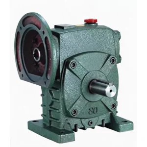
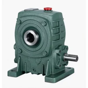
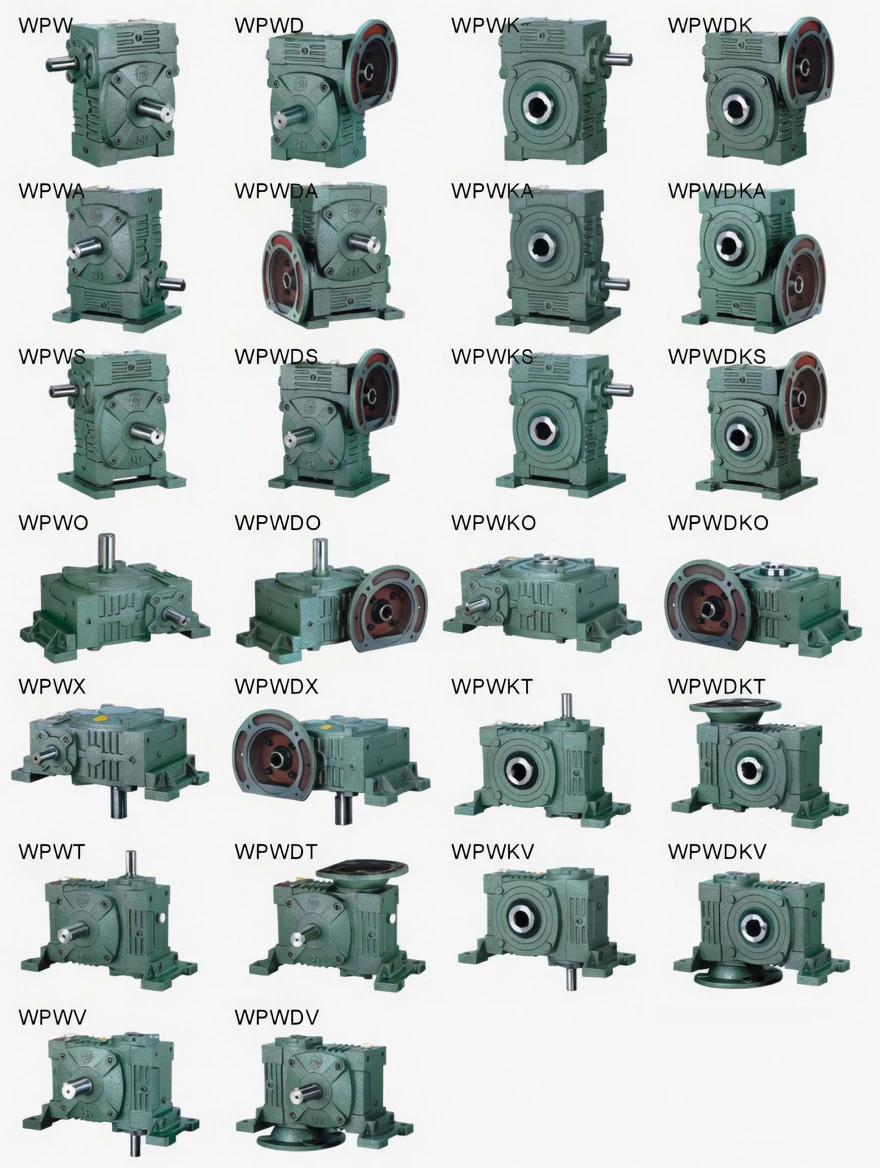
WPWDS Flange-Mounted Universal Worm Gear Reducer with Cooling Fins — Thermally Stable Motor-Direct Universal Drive for Cement, Mining & Hot-Climate Industries
A motor-direct universal worm gearbox in a hot industrial environment faces a triple thermal challenge: motor heat, gear mesh heat, and high ambient temperature all acting simultaneously. Without thermal management, oil sump temperatures approach limits, lubricant degrades rapidly, and overtemperature trips halt production. The WPWDS flange-mounted universal worm gear reducer with cooling fins resolves all three by combining IEC motor direct input, WPW universal flanged-base multi-orientation mounting, and cast-integral cooling fins — maintaining oil sump temperature approximately 15°C lower than the smooth-body WPWD at equivalent load.
This makes the WPWDS the definitive motor-direct universal drive for cement plant conveyors, mining equipment in hot climates, and outdoor industrial machinery where motor-direct convenience AND thermal stability must be specified together. Available in 12 sizes (40–250 mm), motors 0.12–15 kW, ratios 1/5–1/60. About Ever-power | Request a Thermal Assessment
Technical Specifications
WPWDS shares the specification drawing with WPWDA. HL = housing height including fins (greater than WPWD smooth-body). All flange and base dimensions identical to WPWD — direct thermal upgrade with HL clearance check. Reference speed 1500 r/min. All dimensions in mm.
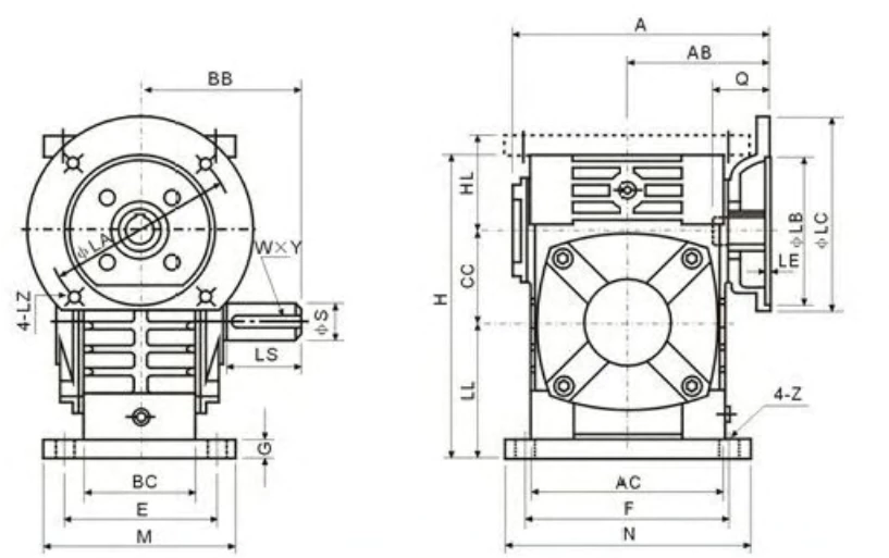
| Size | Power(kW) | Ratio | A | AB | BB | AC | BC | CC | HL | LL | H | M | N | E | F | G | Z | LA | LB | LC | LE | LZ | Q | U | T×V | LS | S | W×Y | Wt(kg) | |
|---|---|---|---|---|---|---|---|---|---|---|---|---|---|---|---|---|---|---|---|---|---|---|---|---|---|---|---|---|---|---|
| 40 | 0.12 | 1/5–1/60 | 135 | 75 | 74 | 95 | 61 | 40 | 45 | 60 | 135 | 100 | 130 | 80 | 110 | 10 | 10 | 115 | 95 | 140 | 4 | M8 | 31 | 11 | 4×12.8 | 28 | 14 | 5×3 | 5 | |
| 50 | 0.18 | 151 | 83 | 97 | 111 | 68 | 60 | 80 | 93 | 195 | 130 | 150 | 100 | 105 | 120 | 18 | 12 | 115 | 95 | 140 | 4 | M8 | 31 | 11 | 4×12.8 | 40 | 17 | 5×3 | 8 | |
| 60 | 0.37 | 157 | 91 | 112 | 127 | 76 | 60 | 80 | 93 | 195 | 130 | 150 | 100 | 105 | 120 | 18 | 12 | 130 | 110 | 160 | 4 | M8 | 33 | 14 | 5×16.3 | 50 | 22 | 7×4 | 12.5 | |
| 70 | 0.37/0.75 | 200/222 | 109/111 | 131 | 152 | 86 | 70 | 73 | 108 | 233 | 150 | 190 | 115 | 150 | 18 | 15 | 130/165 | 110/130 | 160/200 | 4 | M8/M10 | 40/42 | 14/19 | 5×16.3/6×21.8 | 60 | 28 | 7×4 | 17 | ||
| 80 | 0.75/1.5 | 225 | 125 | 142 | 169 | 102 | 80 | 83 | 123 | 268 | 170 | 220 | 135 | 180 | 18 | 15 | 165 | 130 | 200 | 4.5 | M10 | 48/52 | 19/24 | 6×21.8/8×27.3 | 65 | 32 | 10×4.5 | 26 | ||
| 100 | 1.5 | 280 | 148 | 169 | 216 | 117 | 100 | 100 | 150 | 330 | 190 | 270 | 155 | 220 | 20 | 15 | 165 | 130 | 200 | 4.5 | M10 | 52 | 24 | 8×27.3 | 75 | 38 | 10×4.5 | 41.5 | ||
| 120 | 2.2/3.0 | 333 | 181 | 190 | 256 | 124 | 120 | 120 | 180 | 395 | 230 | 320 | 180 | 260 | 25 | 18 | 215 | 180 | 250 | 5 | M12 | 63 | 28 | 8×31.3 | 85 | 45 | 12×4.5 | 60 | ||
| 135 | 3.0/4.0 | 375 | 202 | 210 | 296 | 147 | 135 | 135 | 215 | 450 | 250 | 350 | 200 | 290 | 30 | 18 | 215 | 180 | 250 | 5 | M12 | 63 | 28 | 8×31.3 | 95 | 55 | 16×6 | 90 | ||
| 155 | 5.5 | 448 | 247 | 252 | 345 | 185 | 155 | 135 | 235 | 493 | 280 | 380 | 220 | 320 | 32 | 21 | 265 | 230 | 300 | 5 | M12 | 83 | 38 | 10×41.3 | 110 | 60 | 18×7 | 118 | ||
| 175 | 7.5 | 481 | 262 | 255 | 374 | 192 | 175 | 160 | 260 | 558 | 310 | 410 | 250 | 350 | 37 | 21 | 265 | 230 | 300 | 5 | M12 | 83 | 38 | 10×41.3 | 110 | 65 | 18×7 | 167 | ||
| 200 | 11.0 | 543 | 285 | 319 | 412 | 230 | 200 | 175 | 290 | 620 | 355 | 445 | 290 | 390 | 45 | 24 | 300 | 250 | 350 | 6 | M16 | 114 | 42 | 12×45.3 | 125 | 70 | 20×7.5 | 237 | ||
| 250 | 11.0/15.0 | 615 | 330 | 385 | 500 | 285 | 250 | 200 | 350 | 750 | 460 | 560 | 380 | 480 | 50 | 28 | 300 | 250 | 350 | 6 | M16 | 114 | 42 | 12×45.3 | 155 | 90 | 25×9 | 395 |
* Shared specification drawing with WPWDA. HL = height including fin array — greater than WPWD equivalent. All other dimensions (A, AB, BB, AC, BC, flange LA/LB/LC, shaft LS/S/W×Y) identical to WPWD — direct thermal upgrade with HL height clearance verification.
Product Structure — IEC Flange + Universal Base + Cast-Integral Fins
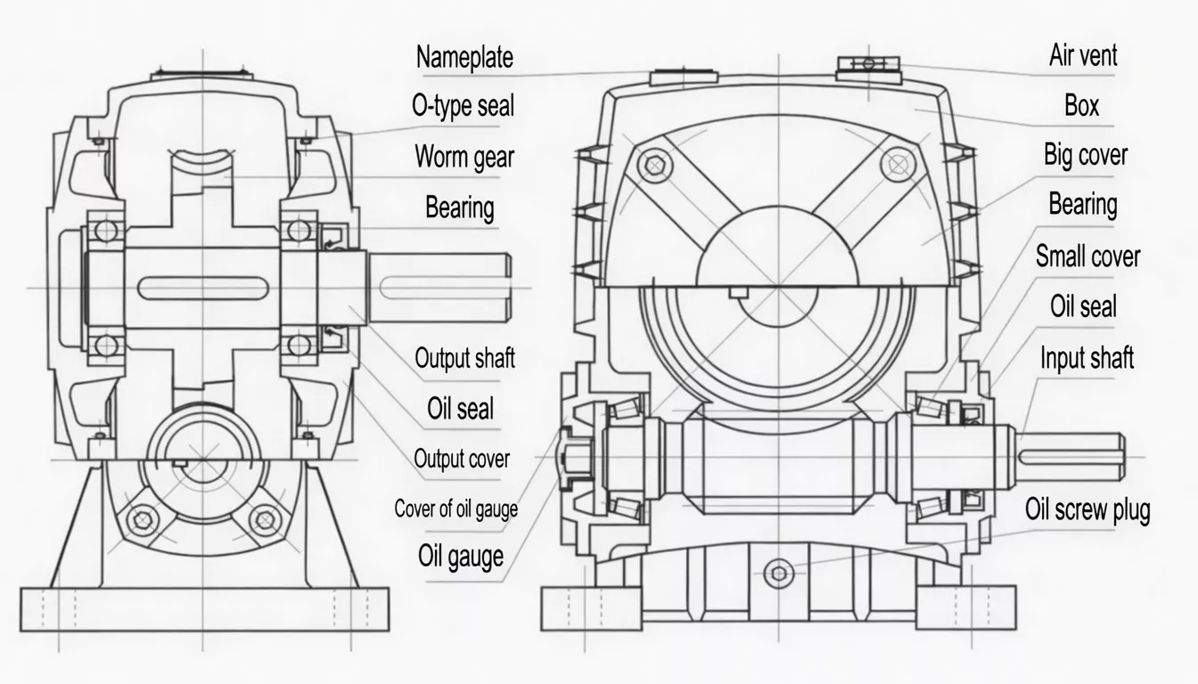
The WPWDS integrates three features in one FC25 cast iron housing: the IEC motor flange at the input, the WPW universal flanged base at the mounting structure, and a cast-integral longitudinal fin array on the housing top and outer side faces. All three features are part of the same foundry casting — no bolt-on accessories, no vibration risk, permanent thermal performance throughout the service life.
| Motor Input | IEC 60034-7 flange + keyed bore — motor shaft direct, no coupling |
| Cooling Fins | Cast-integral longitudinal fins — ~15°C lower vs WPWD at rated load |
| Base | Universal flanged base (AC, BC) — multi-orientation mounting |
| Motor Range | 0.12 kW (size 40) to 15 kW (size 250) |
| Upgrade Path | Direct thermal upgrade from WPWD — same dims, verify HL clearance |
| Housing | FC25 cast iron; all three features integral — no bolt-on additions |
✅ Key Features & Benefits
Three Thermal Sources — One Integrated Solution
A motor-direct drive in a hot environment generates heat from: (1) the motor winding, (2) the gear mesh. The WPWDS fin array manages both heat loads simultaneously, maintaining oil temperature ≤90°C even at 40–43°C ambient and rated load — the only motor-direct universal gearbox in the WPW series with this capability. Keywords: motor-direct cooling fins universal worm reducer, thermal IEC flange worm gearbox.
IEC Direct Motor Input + Fin Cooling — Both in One Unit
No other WPW series product combines IEC motor direct mounting AND integral cooling fins. WPWD has motor-direct but no fins; WPWS has fins but no motor-direct. The WPWDS delivers both, making it the only motor-direct universal drive suited to continuous heavy-duty service in hot industrial environments.
Universal Mounting in Hot Environments
The WPW universal flanged base allows the WPWDS to be installed at any supported orientation in cement plants, mining sites, and outdoor tropical equipment — with correct oil lubrication confirmed for each position. The fin cooling performance is verified across all rated mounting positions.
Extended Lubricant Life Under Motor + Gear Heat
Reducing oil sump temperature by 15°C approximately doubles lubricant oxidation life. In motor-direct applications (where motor heat adds to gear heat), the WPWDS’s thermal advantage is even more valuable than for a standard non-motor-direct drive. Oil drain intervals can typically be extended from 2,500 to 3,500+ hours in WPWDS continuous applications.
Permanent Cast-Integral Fins for Industrial Durability
The fins are cast as part of the housing body — not a separate heat sink that can loosen under the vibration and thermal cycling of cement and mining environments. Permanent thermal performance throughout the WPWDS service life with no fin-related maintenance required.
Direct Thermal Upgrade from WPWD
WPWDS shares all dimensions (A, AB, flange LA/LB/LC, shaft LS/S) with WPWD. For any WPWD installation experiencing overtemperature issues, WPWDS is the minimum-disruption upgrade — verify HL height clearance for the fin array and swap in place.
Industry Applications
The WPWDS is specified wherever IEC motor-direct convenience AND thermal stability under continuous load in hot environments are both required:
Cement Plant Motor-Direct DrivesIEC motor-direct conveyor drives in cement plants where ambient temperatures reach 45°C+ and continuous duty demands both the convenience of motor-direct mounting and the thermal stability of fin cooling.
Mining Equipment in Hot ClimatesMotor-direct drives for mining conveyors and auxiliary equipment in hot climate open-cast and underground mines where the combination of motor heat and 40°C+ ambient temperature would push smooth-body WPWD units beyond their thermal limits.
Outdoor Tropical Industrial DrivesAny outdoor motor-direct universal drive in Gulf region, South Asian, or tropical environments where WPWD thermal limits are approached during summer peak loads.
Chemical Plant Continuous DrivesMotor-direct conveyor and auxiliary drives in continuous chemical process plants running 24/7 in enclosed warm plant rooms where the WPWDS fin array manages the combined heat load of motor and gearbox.
Biomass & Energy EquipmentMotor-direct conveyor drives for biomass handling, wood chip processing, and bioenergy plants in outdoor or warm enclosed environments where motor-direct convenience is required alongside thermal stability.
Glass & Ceramic IndustryIEC motor-direct drives for glass batch conveyors, kiln car drives, and ceramic factory production line conveyors in hot plant rooms where standard motor-direct units lack the thermal headroom for continuous operation.
Quality Control & Certification
ISO 9001:2015 & CE
Full ISO 9001:2015 QMS. CE Declaration of Conformity. Fin casting quality verified at foundry stage before machining. SGS/BV inspection available for cement and mining sector procurement documentation.
️ Thermal Run + IEC Flange Verification
Each WPWDS undergoes: (1) IEC flange CMM check (≤0.05 mm TIR); (2) 60-min thermal stability run at 110% rated torque — temperature must stabilise ≤90°C, confirming the fin array manages the combined motor and gear heat load; (3) noise ≤72 dB(A) and seal integrity verification.
Material & Fin Standards
Housing and fins: FC25 cast iron (≥250 MPa). Worm: 20CrMnTi (≥58 HRC). Wheel: ZCuSn10Pb1 tin-bronze. Fin geometry verified at foundry stage. Third-party inspection for cement, mining, and glass sector quality audits on request.
Why Choose Ever-power for WPWDS Gearboxes
We supply WPWDS thermally optimised motor-direct universal worm gearboxes to cement plant equipment builders, mining machinery OEMs, and outdoor industrial equipment manufacturers in Korea, India, the UK, Australia, and over 60 countries. Our 60-minute thermal stability test — with pass criterion set at ≤90°C (not just the 95°C maximum) — reflects our commitment to delivering units that perform reliably in the hottest real-world environments our customers face.
- ✅ 60-min thermal run at 110% torque — pass ≤90°C, every unit
- ✅ IEC flange CMM + thermal run combined test — both verified per shipment
- ✅ Foundry-stage fin geometry inspection before machining
- ✅ Thermal simulation service — model ambient and duty cycle before ordering
- ✅ 20+ years export record — Korea, India, UK, Australia and beyond
⭐ Customer Reviews
“We upgraded our clinker conveyor motor-direct drives from WPWD to WPWDS after summer overtemperature trips. The improvement is dramatic — the WPWDS units run 14°C cooler on the same duty cycle and we’ve had zero thermal trips in 18 months. The IEC flange motor mounting makes maintenance faster, and the fin cooling handles our 42°C Queensland summer ambient. Best upgrade decision we’ve made on this plant.”
Craig O., Drive Systems Engineer
Cement Plant, Queensland, Australia
“We specify WPWDS for all motor-direct universal drives on our mining conveyor equipment destined for Southeast Asian markets. The fin cooling provides the thermal headroom for 45°C+ outdoor ambient temperatures that standard WPWD units cannot handle reliably at full load. Consistent quality from Ever-power across multiple project supply programmes.”
Jae-won K., Senior Engineer
Mining Equipment OEM, Busan, South Korea
“WPWDS on our cement conveyor motor-direct drives. Maharashtra summer temperatures reach 46°C and our drives run 16 hours per day. The finned units handle these conditions without overtemperature alarms — the smooth WPWD units we previously had were marginal at this temperature. Oil intervals have extended significantly. Very satisfied.”
Priya S., Plant Engineer
Cement Works, Maharashtra, India
“WPWDS for our glass batch conveyor motor-direct drives in a hot plant room. The three-feature combination — motor-direct, universal base, and fin cooling — is exactly what our installation requires. The 60-min thermal test report provided with each unit is a useful QA document for our engineering records. Minor query on one delivery resolved promptly.”
Tom H., Maintenance Manager
Glass Manufacturing, Stoke-on-Trent, UK
❓ Frequently Asked Questions
What is the difference between WPWDS and WPWD?
The WPWD has an IEC motor flange on a universal flanged-base housing with a smooth body. The WPWDS has the identical motor flange and base but adds cast-integral cooling fins that reduce sustained oil temperature by ~15°C. All flange, base, and shaft dimensions are identical — WPWDS is a direct thermal upgrade for WPWD with HL height clearance check.
How does the WPWDS handle the combined heat from motor and gearbox?
The motor generates heat that enters the gearbox housing through the flange interface, adding to the gear mesh heat. The WPWDS fin array is sized to dissipate this combined heat load at rated conditions (up to 43°C ambient with standard mineral ISO VG 320 oil). Our 60-minute thermal test at 110% rated torque verifies this combined thermal management before every unit ships.
At what ambient temperature can the WPWDS operate continuously?
With standard ISO VG 320 mineral oil, the WPWDS can typically operate at rated motor-direct load continuously in ambient temperatures up to 43–45°C without exceeding the 95°C oil temperature limit. With synthetic PG ISO VG 460 oil, this extends to approximately 48–50°C. Contact us for a precise calculation for your specific motor power, ratio, and ambient conditions.
Can I replace a WPWD with a WPWDS without changing the motor or machine structure?
Yes — all motor flange dimensions (LA, LB, LC, LE, LZ) and base footprint dimensions are identical between WPWD and WPWDS. The only difference is the increased HL (housing height) due to the cooling fin array. Measure the available vertical clearance above your existing WPWD before ordering WPWDS as a thermal upgrade.
Does the WPWDS support all the same mounting orientations as the WPWD?
Yes — WPWDS supports the same WPW universal platform orientations as WPWD, with multi-face oil ports for correct lubrication in each position. The fin array position is fixed on the housing; for vertical mounting orientations, the fins are on the housing side rather than the top face, which slightly reduces natural convection effectiveness. Contact us for a position-specific thermal assessment if required.
Motor-Direct + Thermal Stability — Get WPWDS Quote Today
If your WPWD is overheating in hot industrial service, or you need a motor-direct universal drive engineered for hot environments from the start, the WPWDS is the answer. Get a free thermal calculation for your ambient and duty cycle.