説明
WPES Double Speed Worm Gear Reducer with Cooling Fins — Solving the Dual Thermal Challenge of Two-Stage Continuous Heavy-Duty Drives
A two-stage worm gearbox presents a unique thermal challenge: two gear meshes generating heat simultaneously, in a housing that must be thermally stable enough for continuous duty in cement plants, metallurgical facilities, and 24/7 heavy process lines. The WPES double speed worm gear reducer is the purpose-engineered answer — combining the ultra-high reduction ratios (1/200–1/900) of the WPE two-stage design with deep integral cooling fins that dramatically extend natural convection surface area.
The result is a thermally optimised two-stage worm gearbox that maintains oil sump temperatures up to 18°C lower than the equivalent smooth-body WPEA at rated load — extending lubricant service life, protecting seals, and preventing overtemperature trips in hot plant rooms. Available in 9 size groups (40-70 through 155-250 mm), 5 shaft-direction positions, ratios 1/200 to 1/900. エバーパワーについて | Request a Thermal Assessment
Technical Specifications
WPES shares the WPEA base footprint but with a significantly increased housing height (HL) due to the fin array. HH = housing height including fins. Reference input speed 1500 r/min. All dimensions in mm.
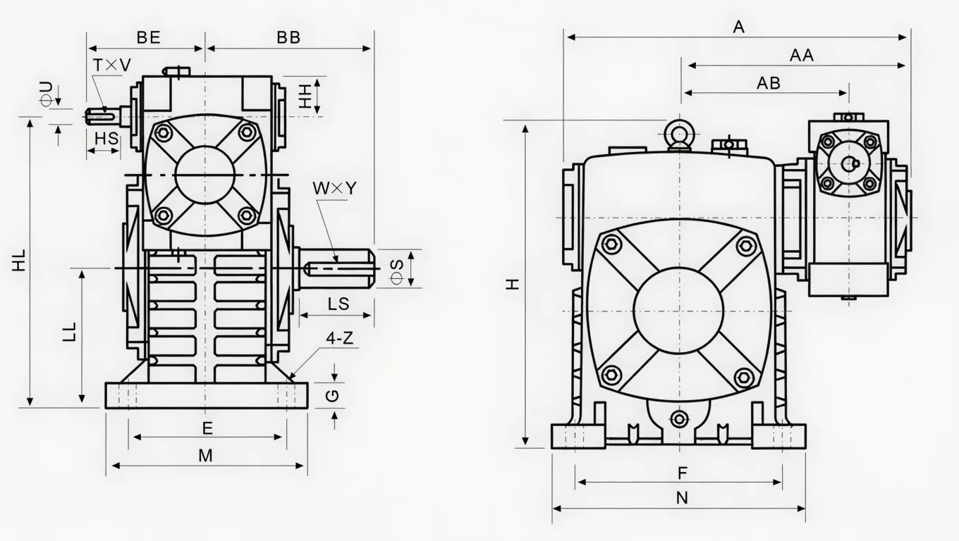
| Size | Ratio | A | AA | AB | BB | BE | HL | LL | H | HH | M | N | E | F | G | Z | HS | U | T×V | LS | S | W×Y | Wt(kg) |
|---|---|---|---|---|---|---|---|---|---|---|---|---|---|---|---|---|---|---|---|---|---|---|---|
| 40-70 | 1/200–1/900 | 286 | 195 | 153 | 131 | 87 | 215 | 105 | 238 | 35 | 150 | 190 | 115 | 150 | 20 | 15 | 25 | 12 | 4×2.5 | 60 | 28 | 7×4 | 20 |
| 50-80 | 297 | 197 | 144 | 142 | 108 | 250 | 120 | 273 | 35 | 170 | 220 | 135 | 180 | 20 | 15 | 30 | 12 | 4×2.5 | 65 | 32 | 10×4.5 | 27 | |
| 60-100 | 363 | 231 | 175 | 169 | 120 | 310 | 150 | 334 | 42 | 190 | 270 | 155 | 220 | 25 | 15 | 40 | 15 | 5×3 | 75 | 38 | 10×4.5 | 45 | |
| 70-120 | 408 | 256 | 193 | 190 | 140 | 370 | 180 | 423 | 55 | 230 | 320 | 180 | 260 | 30 | 18 | 40 | 18 | 5×3 | 85 | 45 | 12×4.5 | 73 | |
| 80-135 | 471 | 298 | 226 | 210 | 160 | 430 | 215 | 482 | 65 | 250 | 350 | 200 | 290 | 30 | 18 | 50 | 22 | 7×4 | 95 | 55 | 16×6 | 101 | |
| 100-155 | 555 | 354 | 269 | 252 | 190 | 490 | 235 | 541 | 80 | 275 | 390 | 220 | 320 | 35 | 21 | 50 | 25 | 7×4 | 110 | 60 | 18×7 | 147 | |
| 120-175 | 598 | 379 | 287 | 255 | 219 | 555 | 260 | 600 | 95 | 310 | 430 | 250 | 350 | 40 | 21 | 65 | 30 | 7×4 | 110 | 65 | 18×7 | 204 | |
| 135-200 | 580 | 318 | 319 | 202 | 625 | 290 | 677 | 105 | 360 | 480 | 290 | 390 | 40 | 24 | 75 | 35 | 10×4.5 | 125 | 70 | 20×7.5 | 298 | ||
| 155-250 | 795 | 510 | 380 | 385 | 205 | 755 | 350 | 824 | 103 | 460 | 560 | 380 | 480 | 45 | 28 | 85 | 40 | 12×5 | 155 | 90 | 25×9 | 462 |
* HL = full housing height including fin array; HH = lateral height offset. WPES shares identical base footprint (A, B, CC dimensions) with WPEA — direct thermal upgrade with H clearance verification required.
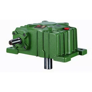
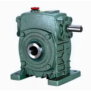
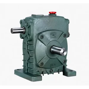
Product Structure — Two-Stage Housing with Integral Fin Array
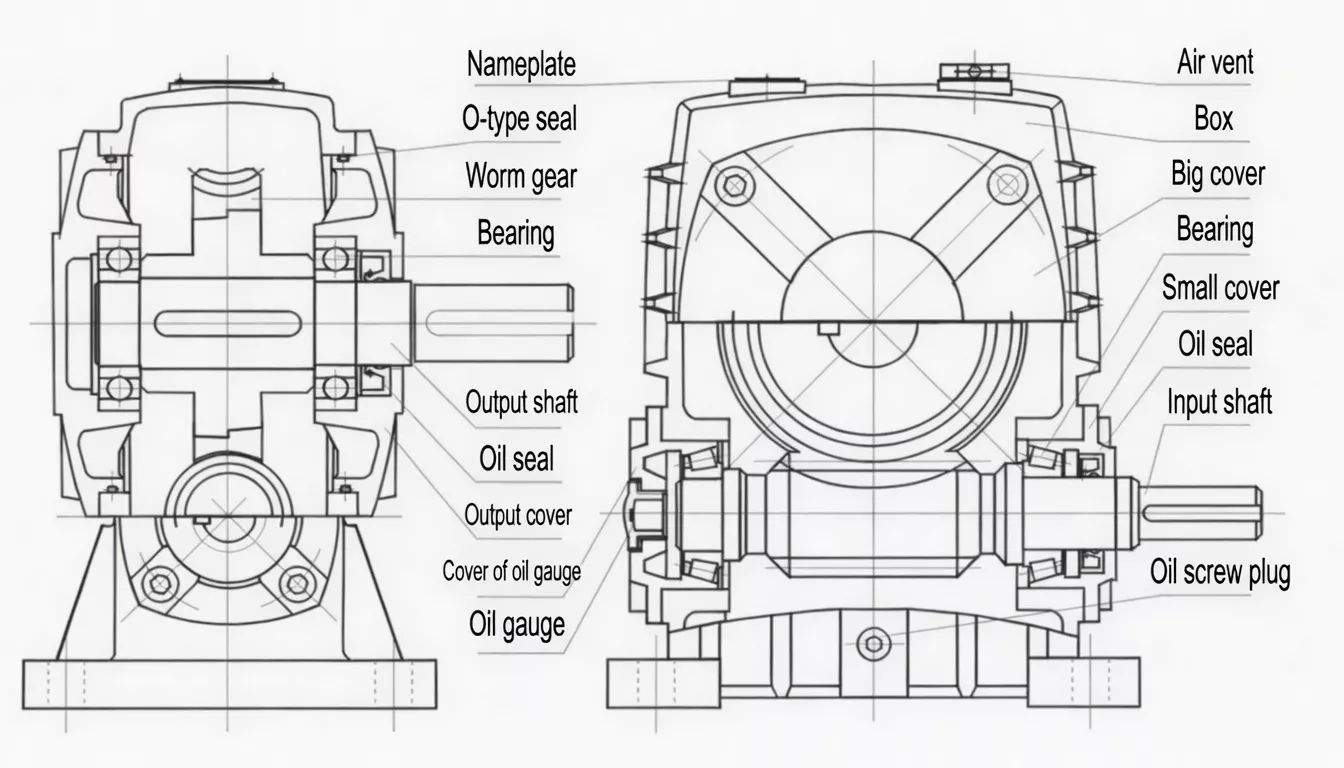
The WPES elongated two-stage housing features cast-integral longitudinal fins on the top and outer side faces — the faces with the highest natural convection exposure in a foot-mounted installation. Both worm gear stages share the single oil bath, and the expanded fin array ensures that heat generated by both gear meshes can be dissipated by natural convection without exceeding the 95°C maximum sump temperature limit even in 40°C+ ambient conditions.
| Stages | Two worm-and-wheel pairs in series; shared oil bath |
| Cooling Fins | Cast-integral longitudinal fins; up to +45% surface area vs WPEA; ~18°C cooler at rated load |
| Ratio Range | 1/200 – 1/900 two-stage combined |
| Housing | FC25 cast iron; same base footprint as WPEA, increased height for fins |
| Worm Pairs | 20CrMnTi (≥58 HRC) + ZCuSn10Pb1 bronze; both stages |
| Thermal Gain | ~18°C lower steady-state vs WPEA; accommodates 40°C+ ambient without supplemental cooling |
✅ Key Features & Benefits
Solves the Two-Stage Heat Problem
Two gear meshes means two sources of friction heat in one housing. The WPES fin array is sized to dissipate the combined thermal output of both worm pairs at rated load, preventing the cumulative heating that causes premature lubricant degradation and seal failure in smooth-body two-stage units. Keywords: thermally stable two-stage worm gearbox, double speed reducer with cooling.
~18°C Lower Temperature vs WPEA
At rated load and 40°C ambient, the WPES oil sump temperature is approximately 18°C lower than the equivalent WPEA — a greater differential than the ~15°C achieved by the WPS single-stage fin variant, because the WPES fins must manage dual-stage heat generation. This margin keeps the unit within the 95°C maximum limit even in hot cement, metallurgical, and outdoor environments.
Cast-Integral Fins — Permanent Performance
The cooling fins are cast as part of the housing in a single foundry pour, ensuring maximum thermal conductivity and permanent bond to the housing body. Unlike bolt-on heat sink accessories, there is no risk of fin loosening under the vibration and thermal cycling inherent in cement plant and mining environments.
Extended Lubricant Life in Two-Stage Applications
Two-stage worm units run hotter than single-stage equivalents at the same input power. The WPES fin array reduces this temperature excess, extending ISO VG 320 mineral oil drain intervals from the 2,500-hour standard up to 3,500–4,000 hours in many continuous applications — a meaningful reduction in maintenance intervention frequency for remote or difficult-to-access drives.
Drop-In Thermal Upgrade from WPEA
The WPES shares the identical base footprint, shaft dimensions, and shaft-direction options with the WPEA. Where an installed WPEA is experiencing overtemperature issues in a hot plant room, the WPES is the minimum-disruption upgrade — verify the available height clearance for the fin array (HL difference) and swap in place.
Five Shaft-Direction Options
Standard positions A through E provide full installation flexibility for the WPES in the demanding environments where it is most needed — mine drives, cement plants, and chemical process lines — without requiring angle-drive accessories.
Industry Applications
The WPES is the thermal management solution for two-stage worm drives in the world’s most demanding high-temperature industrial environments:
Cement & Lime ProductionKiln slow drives, clinker conveyor drives, and raw mill auxiliaries in hot cement plants where the WPES handles dual-stage heat generation in ambient temperatures up to 50°C without supplemental cooling.
Metallurgy & Rolling MillsRolling mill main drive auxiliaries, bloom transfer table drives, and blast furnace charging equipment where continuous operation in high-ambient-temperature steel plant environments demands thermally stable two-stage drives.
Mining — Hot Climate ApplicationsUnderground mine conveyors in deep hot mines (West Africa, India, Australia) and surface mineral processing plants in desert environments where ambient temperatures regularly exceed 40°C.
Chemical Process — Continuous LinesContinuous stirred-tank reactor (CSTR) drives and large agitator systems in chemical plants operating at 90%+ duty cycle in enclosed, poorly-ventilated plant rooms.
24/7 Heavy Industrial ProcessesGlass furnace batch charger drives, rubber vulcanisation line auxiliaries, and any continuous industrial process operating three shifts per day where two-stage gearbox overheating has been a recurring maintenance issue.
Outdoor & Tropical ApplicationsIrrigation pump station drives, sugar mill conveyor drives, and biomass processing equipment in tropical and subtropical regions where outdoor ambient temperatures exceed 45°C during summer production periods.
Quality Control & Certification
ISO 9001:2015 & CE
Full ISO 9001:2015 QMS. CE Declaration of Conformity per shipment. Fin casting quality is inspected at the foundry stage — incomplete fin fill, voids, or geometric deviation from spec are grounds for rejection before any machining commences.
️ Dual-Stage Thermal Run Test
Each WPES undergoes a 90-minute thermal stability run at 110% rated torque with oil sump temperature measured at both gear stages. Temperature must stabilise below 95°C and the differential between the two stages must be within 8°C of each other, confirming that fin cooling is uniformly effective across the full two-stage housing length.
️ Material & Fin Standards
Housing: FC25 cast iron (≥250 MPa). Both worm shafts: 20CrMnTi (≥58 HRC). Wheel rims: ZCuSn10Pb1 tin-bronze. Fin pitch, height, and wall thickness verified against drawing spec. Third-party SGS/BV inspection available for cement, steel, and chemical industry quality audits.
Why Choose Ever-power for WPES Double Speed Gearboxes
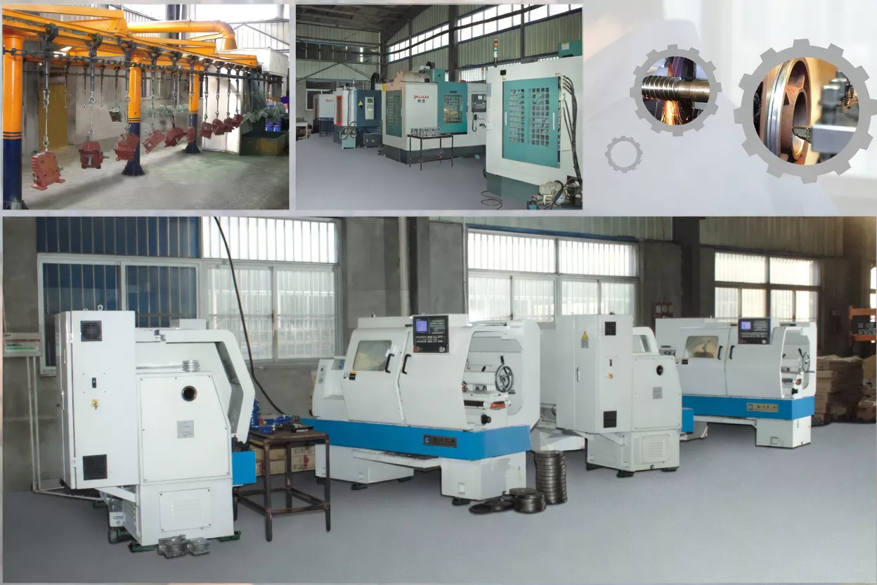
We supply WPES thermally optimised two-stage worm gearboxes to cement OEMs, steel mill equipment builders, and chemical plant machinery manufacturers in the UK, Korea, India, Australia, and beyond. Our in-house foundry applies dedicated quality control for the WPES fin casting — fin geometry is verified at casting stage, not just after machining — ensuring consistent thermal performance across every unit.
- ✅ Foundry-stage fin geometry inspection — before machining, not after
- ✅ Dual-stage thermal run test as standard — 90-minute at 110% rated torque
- ✅ Thermal simulation capability — model your duty cycle and ambient temperature
- ✅ OEM supply for cement & steel OEMs — batch consistency across production programmes
- ✅ 20+ years export experience — UK, Korea, India, Australia and beyond
⭐ Customer Reviews
“We upgraded our kiln slow drive from WPEA to WPES after experiencing recurrent overtemperature trips during Queensland summer. The difference is substantial — the WPES runs 16°C cooler on the same duty cycle and we have had zero thermal trips in 14 months since the upgrade. The fin array on the two-stage housing is clearly doing its job.”
Patrick L., Drive Systems Engineer
Cement Works, Queensland, Australia
“We use WPES-100/155 units on our rolling mill auxiliary conveyor drives in a plant room where ambient temperatures regularly reach 48°C. The units run continuously three shifts per day and have been thermally stable throughout two years of operation. Oil change intervals have extended to 3,500 hours as our lubrication team predicted. Excellent product.”
Ian S., Maintenance Manager
Integrated Steel Works, South Wales, United Kingdom
“We operate continuous chemical process lines at near-100% duty cycle in enclosed plant rooms. The WPES-80/135 units on our heavy agitator drives have maintained stable sump temperatures through our hottest summer production season. The two-stage drive with fins is exactly the right combination for our application. Very satisfied with Ever-power quality and support.”
Park J., Senior Engineer
Chemical Process Plant, Ulsan, South Korea
“We use WPES gearboxes on our limestone crusher conveyor drives. Rajasthan summer temperatures exceed 45°C and our plant rooms are poorly ventilated. The finned two-stage units handle these conditions far better than our previous smooth-body units. One documentation delay on a batch order but resolved satisfactorily by Ever-power.”
Ramesh P., Plant Engineer
Limestone Processing Plant, Rajasthan, India
❓ Frequently Asked Questions
How much cooler does the WPES run compared to the WPEA?
In two-stage operation at rated load and 40°C ambient, the WPES maintains oil sump temperature approximately 15–18°C lower than an equivalent WPEA. The differential is slightly higher than for single-stage variants (WPES vs WPEA > WPS vs WPA) because both gear stages contribute to the heat load that the fins must dissipate. At 45°C ambient and 110% overload, the differential can exceed 20°C — potentially the critical margin between normal operation and an overtemperature trip.
What is the maximum ambient temperature for WPES continuous operation?
With standard ISO VG 320 mineral oil, the WPES can operate continuously at rated load in ambient temperatures up to approximately 45°C without exceeding the 95°C oil sump temperature limit. With synthetic PG ISO VG 460 oil, this extends to approximately 50°C. Ensure at least 50 mm of unobstructed air space around the fin array for effective natural convection.
Can I replace an existing WPEA with a WPES without machine modification?
The WPES shares the identical base footprint (A, B, CC dimensions) and shaft dimensions with the WPEA. The only dimensional difference is the increased housing height (HL) due to the cooling fin array — see the HH column in the specification table. Measure the available vertical clearance above your existing WPEA installation and compare to the WPES HL value for your frame size before ordering.
What lubricant is recommended for WPES in very high temperature environments?
For ambient temperatures above 40°C, or applications where two-stage heat generation may push oil sump temperatures above 80°C, we recommend upgrading to synthetic polyalkylene glycol (PAG) ISO VG 460. PAG oils have superior thermal stability, higher viscosity indices, and lower friction coefficients than mineral oils — reducing gear mesh heat generation as well as extending drain intervals to 5,000+ hours in many applications.
Does the WPES fin array require maintenance in dusty or dirty environments?
In dusty environments (cement plants, mining), inspect the fin channels annually and clean with compressed air if significant dust accumulation is visible — blocked fins reduce thermal performance. In high-humidity or outdoor environments, ensure fin channels drain freely and do not accumulate standing water. No structural fin maintenance is required; the cast-integral fins cannot loosen or detach regardless of vibration or thermal cycling.
Solve Your Two-Stage Thermal Challenge — Enquire About WPES Today
If your WPEA or competitor two-stage unit is overheating in a hot or enclosed environment, the WPES delivers the thermal headroom you need. Our engineers will assess your duty cycle and provide a free thermal calculation.