Deskripsi
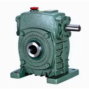
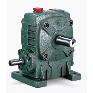
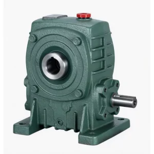
WPWDK Flange-Mounted Universal Hollow Shaft Worm Gear Reducer — Zero Couplings at Both Ends with Universal Multi-Orientation Mounting
Every coupling in a drive system is a maintenance point, an alignment task, and a potential failure mode. The WPWDK flange-mounted universal hollow shaft worm gear reducer eliminates couplings at both the motor input and the driven shaft output simultaneously — IEC flange at the front accepts the motor shaft directly; H7 hollow bore at the back accepts the driven shaft directly. The result is the most mechanically streamlined drive configuration in the entire WPW universal series: motor + WPWDK + driven shaft, three components, zero couplings.
Combined with the WPW universal flanged base supporting multiple mounting orientations, the WPWDK is the definitive motor-direct hollow shaft drive for conveyor roller drives, logistics automation, and machine tool auxiliaries requiring zero-coupling simplicity at any installation angle. Motors 0.12–15 kW, bore 18–110 mm, ratios 1/5–1/60, 12 size groups. About Ever-power | Get a Free Selection Quote
Technical Specifications
Motor flange: LA=OD; LB=pilot OD; LC=bolt circle; LE=bolt count; LZ=bolt size. Input hole: Q, U, T×V. Base: AC, BC, AD, BD, Z×L. Hollow bore: S (H7); W×Y = keyway. Reference speed 1500 r/min. All dimensions in mm.
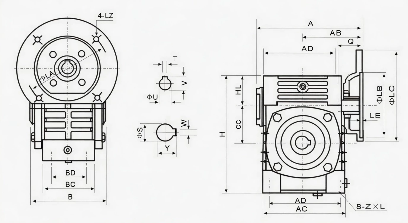
| Size | Power(kW) | Ratio | A | AB | B | AC | BC | AD | BD | CC | HL | H | Z×L | LA | LB | LC | LE | LZ | Q | U | T×V | S(bore) | W×Y | Wt(kg) |
|---|---|---|---|---|---|---|---|---|---|---|---|---|---|---|---|---|---|---|---|---|---|---|---|---|
| 40 | 0.12 | 1/5–1/60 | 135 | 75 | 85 | 95 | 61 | 78 | 42 | 40 | 35 | 125 | M6×12 | 115 | 95 | 140 | 4 | M8 | 31 | 11 | 4×12.8 | 18 | 6×22.8 | 4 |
| 50 | 0.18 | 151 | 83 | 105 | 111 | 68 | 50 | 50 | 35 | 150 | M6×18 | 115 | 95 | 140 | 4 | M8 | 31 | 11 | 4×12.8 | 20 | 6×22.8 | 7 | ||
| 60 | 0.37 | 167 | 91 | 110 | 127 | 76 | 105 | 55 | 60 | 42 | 177 | M8×20 | 130 | 110 | 160 | 4 | M8 | 33 | 14 | 5×16.3 | 25 | 8×28.3 | 10 | |
| 70 | 0.37/0.75 | 200/202 | 109/111 | 130 | 152 | 86 | 125 | 65 | 70 | 55 | 215 | M10×25 | 130/165 | 110/130 | 160/200 | 4 | M8/M10 | 40/42 | 14/19 | 5×16.3/6×21.8 | 30 | 8×33.3 | 14.5 | |
| 80 | 0.75/1.5 | 225 | 125 | 150 | 169 | 102 | 140 | 70 | 80 | 65 | 250 | M12×28 | 165 | 130 | 200 | 4.5 | M10 | 48/52 | 19/24 | 6×21.8/8×27.3 | 35 | 10×38.3 | 23 | |
| 100 | 1.5 | 280 | 148 | 160 | 216 | 117 | 180 | 90 | 100 | 80 | 310 | M12×30 | 165 | 130 | 200 | 4.5 | M10 | 52 | 24 | 8×27.3 | 40 | 12×43.3 | 36.5 | |
| 120 | 2.2/3.0 | 333 | 181 | 175 | 256 | 124 | 220 | 100 | 120 | 95 | 370 | M14×32 | 215 | 180 | 250 | 5 | M12 | 63 | 28 | 8×31.3 | 45 | 14×48.8 | 54 | |
| 135 | 3.0/4.0 | 375 | 202 | 210 | 296 | 147 | 260 | 110 | 135 | 105 | 425 | M16×35 | 215 | 180 | 250 | 5 | M12 | 63 | 28 | 8×31.3 | 60 | 18×64.4 | 83 | |
| 155 | 5.5 | 448 | 247 | 256 | 345 | 185 | 280 | 120 | 155 | 103 | 461 | M16×35 | 265 | 230 | 300 | 5 | M12 | 83 | 38 | 10×41.3 | 70 | 20×74.9 | 110 | |
| 175 | 5.5/7.5 | 481 | 262 | 282 | 374 | 192 | 320 | 140 | 175 | 123 | 521 | M16×35 | 265 | 230 | 300 | 5 | M12 | 83 | 38 | 10×41.3 | 80 | 22×85.4 | 156 | |
| 200 | 11.0 | 543 | 285 | 320 | 412 | 230 | 360 | 150 | 200 | 130 | 575 | M20×36 | 300 | 250 | 350 | 6 | M16 | 114 | 42 | 12×45.3 | 85 | 22×90.4 | 222 | |
| 250 | 11.0/15.0 | 615 | 330 | 400 | 500 | 285 | 420 | 190 | 250 | 150 | 700 | M24×42 | 300 | 250 | 350 | 6 | M16 | 114 | 42 | 12×45.3 | 110 | 28×116.4 | 376 |
* HL = housing height including IEC flange. S = hollow bore H7 — driven shaft to h6/js6. W×Y = bore keyway. AC, BC = flanged base width/depth; AD, BD = anchor bolt hole positions. LA, LB, LC per IEC 60034-7.
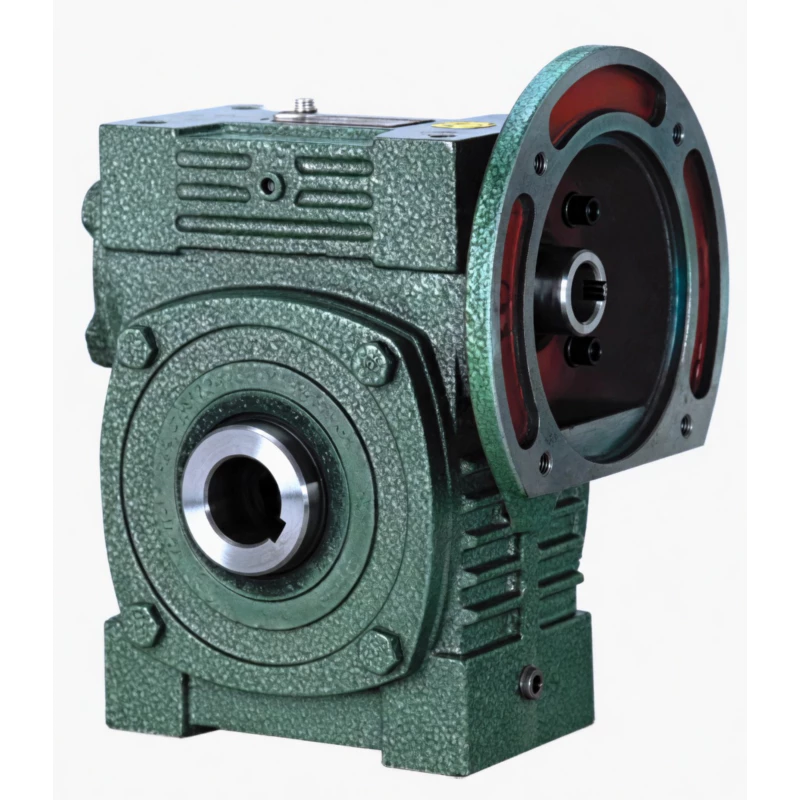
Product Structure — IEC Flange In, Hollow Bore Out, Universal Base Below
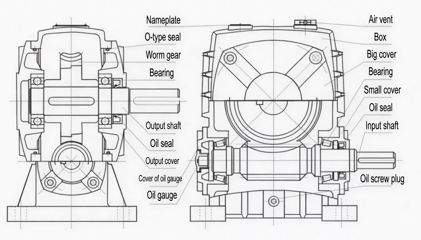
The WPWDK combines three functional elements in one casting: IEC motor flange at the input (LA, LB, LC dimensions), H7 hollow bore at the output (S, W×Y dimensions), and WPW universal flanged base at the mounting interface (AC, BC, AD, BD, Z×L). Motor shaft in at the front; driven shaft in at the back; universal multi-orientation flanged base below. Three interfaces, one housing, zero couplings.
| Motor Input | IEC 60034-7 flange + keyed bore — direct, no coupling |
| Output | H7 hollow bore + keyway; 18–110 mm — direct, no coupling |
| Base | Universal flanged base; multi-orientation; 4 anchor bolt positions |
| Result | Motor + WPWDK + driven shaft — 3 components, 0 couplings |
| Motor Range | 0.12 kW (size 40) to 15 kW (size 250) |
| Self-Locking | At ratios ≥1/30 in all supported orientations |
✅ Key Features & Benefits
Zero Couplings at Both Ends — On a Universal-Mount Platform
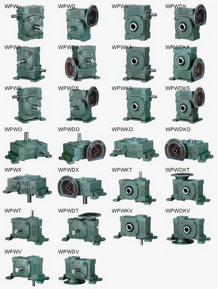
No other WPW product eliminates couplings at both the motor and driven shaft ends AND provides multi-orientation universal mounting simultaneously. WPWD eliminates the motor coupling but has solid shaft output. WPWK eliminates the output coupling but uses standard input shaft. WPWDK eliminates both — on the universal platform. Keywords: zero-coupling universal worm reducer, IEC flange hollow shaft universal gearbox.
15-Minute Motor Swap at Any Mounting Angle
IEC pilot register enables motor change in under 15 minutes regardless of whether the unit is horizontal, inclined, or vertical. For conveyor systems and logistics facilities with multiple installed units at varied angles, this consistent maintenance procedure reduces per-motor service time regardless of orientation.
Hollow Bore Direct Shaft — No Alignment Required at Output
H7 bore accepts the driven shaft without field reaming, coupling hub fitting, or alignment tools. Combined with the IEC flange motor input, the entire WPWDK installation procedure involves: motor bolting (IEC flange) + shaft insertion (hollow bore) + base anchor bolting. No alignment tasks anywhere in the drive chain.
Universal Mounting — One Product for All Machine Orientations
The WPW flanged base multi-orientation capability allows one WPWDK specification to cover horizontal, inclined, and near-vertical conveyor and machine drives. OEM machine builders standardising on WPWDK carry one SKU for all machine variants regardless of mounting angle.
Widest Motor Range in the DK Series — 0.12 to 15 kW
Twelve size groups accepting 0.12 kW to 15 kW cover the complete range of zero-coupling universal drive requirements — from small packaging machine indexing drives (size 40) to large industrial conveyor head drives (size 250).
Self-Locking in All Orientations
At ratios ≥1/30, the WPWDK self-locks in any supported orientation — providing passive load holding at both shaft ends simultaneously (motor side locked by the IEC keyed bore; driven shaft side locked by the hollow bore keyway). No additional holding brake required in many conveyor and machine applications.
Industry Applications
The WPWDK is specified wherever zero-coupling motor-to-shaft drive simplicity is required at any mounting angle:
Conveyor & Logistics AutomationRoller conveyor direct hollow shaft drives, logistics sortation system drives, and high-density automated warehouse conveyor systems where zero-coupling direct shaft mounting simplifies installation and eliminates coupling maintenance at every drive point.
Automotive Production LinesAutomotive assembly line conveyor hollow shaft drives, engine line transport conveyor drives, and car body line conveyor systems where the WPWDK zero-coupling specification is replicated across hundreds of identical drive points.
Food Processing ConveyorsFood production line hollow shaft conveyor roller drives, bakery conveyor direct shaft drives, and food sorting system conveyor drives where the zero-coupling clean design reduces food contamination risk points.
Machine Tool AuxiliariesCNC machining centre auxiliary hollow shaft drives, industrial press feeding system drives, and production line indexing system hollow shaft drives at varied machine mounting angles.
Agricultural ProcessingAgricultural grain conveyor head hollow shaft drives, crop sorting conveyor direct shaft drives, and agricultural processing line conveyor drives requiring zero-coupling hollow bore at varied installation angles.
General OEM Machine DrivesAny OEM machine builder standardising on a single zero-coupling motor-direct hollow shaft universal gearbox specification across an entire product range — eliminating coupling SKUs and coupling maintenance from their BOM and service documentation.
Quality Control & Certification
ISO 9001:2015 & CE
Full ISO 9001:2015 QMS. CE Declaration of Conformity. Automotive and logistics sector OEM documentation available. IEC flange CMM verified; hollow bore H7 plug gauged; both interfaces checked before run test.
Dual Interface Verification
Each WPWDK undergoes: (1) IEC flange concentricity CMM (≤0.05 mm TIR); (2) bore H7 plug gauge; (3) bore concentricity CMM (≤0.05 mm TIR); (4) 45-min run test — noise ≤72 dB(A), seal integrity, torque ±5%. Both interfaces verified on every unit.
OEM Batch Consistency
For automotive and logistics OEM supply, we maintain batch-to-batch dimensional consistency records for both the IEC flange and hollow bore interfaces — supporting high-volume automated assembly line supply programmes where consistent fit across all units is essential.
Why Choose Ever-power for WPWDK Gearboxes
We supply WPWDK zero-coupling universal hollow shaft worm gearboxes to automotive conveyor OEMs, logistics automation equipment builders, and food processing machine manufacturers in Germany, the USA, Australia, Spain, and over 60 countries. Our dual interface CMM verification — IEC flange concentricity AND hollow bore H7, both checked per unit — ensures every WPWDK delivers correct motor fit AND correct shaft fit right out of the box at any mounting angle.
- ✅ Dual interface CMM verification — IEC flange + bore H7, every unit
- ✅ OEM batch consistency records for automotive/logistics supply
- ✅ Motor compatibility check service — confirm before production
- ✅ Custom bore diameters for non-standard conveyor shaft sizes
- ✅ 20+ years export record — Germany, USA, Australia, Spain and beyond
⭐ Customer Reviews
“We switched our entire roller conveyor product range to WPWDK. The zero-coupling specification at both ends cuts our installation time per drive point by over 60% and eliminates our two most common field service calls — coupling wear and coupling misalignment. The universal base handles all the mounting angles in our conveyor range from one product specification.”
Tom H., Systems Engineer
Conveyor Systems OEM, New South Wales, Australia
“We specify WPWDK as our standard for all zero-coupling conveyor drives on our automotive body line systems. The IEC flange motor mounting and hollow bore shaft engagement eliminate two coupling components from every drive point — across a complete car body line, this is a significant simplification of our BOM and maintenance schedule.”
Stefan K., Machine Design Engineer
Automotive Conveyor OEM, Stuttgart, Germany
“WPWDK in our high-density fulfilment centre conveyor systems. The zero-coupling design at both ends is critical in our maintenance-constrained conveyor topology where access is limited. The multi-orientation universal base means one gearbox specification covers our entire facility layout. Consistent quality and reliable delivery from Ever-power.”
Kevin R., Logistics Engineer
Fulfilment Centre Equipment, Texas, USA
“We use WPWDK for our food production line hollow shaft conveyor drives. The zero-coupling design reduces contamination risk points and the IEC flange makes motor changes clean and fast. Good quality, IEC flange and bore dimensions consistently correct. A good product for food-sector zero-coupling drive applications.”
Jose M., Technical Manager
Food Conveyor Equipment, Barcelona, Spain
❓ Frequently Asked Questions
What makes the WPWDK different from WPWD and WPWK?
The WPWD has IEC motor flange + solid shaft output. The WPWK has standard input shaft + hollow bore output. The WPWDK has both: IEC motor flange at input AND hollow bore at output — eliminating couplings at both ends simultaneously. No other single product in the WPW series achieves this.
What is the WPWDK installation procedure?
(1) Apply anti-gall grease to motor shaft; bolt motor to IEC flange; tighten to specified torque. (2) Apply anti-gall grease to driven shaft; insert shaft into H7 bore; engage keyway; tighten set screw. (3) Bolt base to machine structure using Z×L anchor bolts for your size. Total installation time: typically 20–30 minutes. No alignment tooling, no coupling components.
Can I use the WPWDK with a VSD (variable speed drive)?
Yes — the WPWDK accepts any standard IE2/IE3 VSD-rated IEC motor. For continuous low-speed VSD duty (below 30 Hz), TEFC motor cooling is reduced — consider whether the duty cycle requires the thermally enhanced WPWDKS variant. For standard VSD operation at moderate speed ranges, the standard WPWDK is fully suitable.
What hollow bore diameters are available for the WPWDK?
Standard bore diameters range from 18 mm (size 40) to 110 mm (size 250). The most common range for conveyor and logistics applications is 25–60 mm. Custom bore diameters for OEM supply are available — contact us with your required bore diameter for availability and minimum order.
How does the WPWDK compare to a separate gearbox + two couplings?
One WPWDK replaces: a gearbox + motor coupling + output shaft coupling. For a 50-unit conveyor system: 100 couplings eliminated, 100 alignment procedures eliminated, 100 coupling guard installations eliminated, and two coupling-related failure modes removed from your maintenance schedule. The WPWDK unit cost is higher; the system TCO is typically significantly lower.
Zero Couplings at Both Ends — Get WPWDK Quote Today
Simplify your drive to three components at any mounting angle. Our engineers will confirm motor flange compatibility, bore size, and anchor bolt specification for your application — free of charge.