Deskripsi
WPWDA Flange-Mounted Universal Worm Gear Reducer — Motor-Direct IEC Input with Multi-Direction Output for Vessels, Agitators & Agricultural Equipment
When a chemical reactor, agricultural elevator, or vessel agitator needs both the installation simplicity of motor-direct IEC flange input AND the output shaft direction flexibility to connect directly to a driven shaft at a non-standard angle — without right-angle adapter boxes — the WPWDA flange-mounted universal worm gear reducer delivers both simultaneously. Combining the IEC motor direct input of the WPWD with the extended multi-direction output geometry of the WPWA in one casting, the WPWDA is the most flexible motor-direct drive in the WPW universal series.
Motor powers from 0.12 kW to 15 kW, 12 size groups (40–250 mm), ratios 1/5–1/60. Extended output shaft (LL, M, N, E, F, G dimensions) accommodates vessel agitator head connections and agricultural shaft drives at varied angles. About Ever-power | Request a Motor Compatibility Check
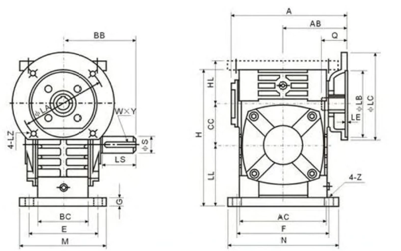
Technical Specifications
WPWDA shares the specification drawing with WPWDS. Motor flange: LA=flange OD; LB=pilot OD; LC=bolt circle; LE=bolt count; LZ=bolt size. Input hole: Q, U, T×V. Output: LS, S, W×Y. Universal base: AC, BC, CC. Extended body: LL, M, N, E, F, G. Reference speed 1500 r/min. All dimensions in mm.
| Size | Power(kW) | Ratio | A | AB | BB | AC | BC | CC | HL | LL | H | M | N | E | F | G | Z | LA | LB | LC | LE | LZ | Q | U | T×V | LS | S | W×Y | Wt(kg) | |
|---|---|---|---|---|---|---|---|---|---|---|---|---|---|---|---|---|---|---|---|---|---|---|---|---|---|---|---|---|---|---|
| 40 | 0.12 | 1/5–1/60 | 135 | 75 | 74 | 95 | 61 | 40 | 45 | 60 | 135 | 100 | 130 | 80 | 110 | 10 | 10 | 115 | 95 | 140 | 4 | M8 | 31 | 11 | 4×12.8 | 28 | 14 | 5×3 | 5 | |
| 50 | 0.18 | 151 | 83 | 97 | 111 | 68 | 60 | 80 | 93 | 195 | 130 | 150 | 100 | 105 | 120 | 18 | 12 | 115 | 95 | 140 | 4 | M8 | 31 | 11 | 4×12.8 | 40 | 17 | 5×3 | 8 | |
| 60 | 0.37 | 157 | 91 | 112 | 127 | 76 | 60 | 80 | 93 | 195 | 130 | 150 | 100 | 105 | 120 | 18 | 12 | 130 | 110 | 160 | 4 | M8 | 33 | 14 | 5×16.3 | 50 | 22 | 7×4 | 12.5 | |
| 70 | 0.37/0.75 | 200/222 | 109/111 | 131 | 152 | 86 | 70 | 73 | 108 | 233 | 150 | 190 | 115 | 150 | 18 | 15 | 130/165 | 110/130 | 160/200 | 4 | M8/M10 | 40/42 | 14/19 | 5×16.3/6×21.8 | 60 | 28 | 7×4 | 17 | ||
| 80 | 0.75/1.5 | 225 | 125 | 142 | 169 | 102 | 80 | 83 | 123 | 268 | 170 | 220 | 135 | 180 | 18 | 15 | 165 | 130 | 200 | 4.5 | M10 | 48/52 | 19/24 | 6×21.8/8×27.3 | 65 | 32 | 10×4.5 | 26 | ||
| 100 | 1.5 | 280 | 148 | 169 | 216 | 117 | 100 | 100 | 150 | 330 | 190 | 270 | 155 | 220 | 20 | 15 | 165 | 130 | 200 | 4.5 | M10 | 52 | 24 | 8×27.3 | 75 | 38 | 10×4.5 | 41.5 | ||
| 120 | 2.2/3.0 | 333 | 181 | 190 | 256 | 124 | 120 | 120 | 180 | 395 | 230 | 320 | 180 | 260 | 25 | 18 | 215 | 180 | 250 | 5 | M12 | 63 | 28 | 8×31.3 | 85 | 45 | 12×4.5 | 60 | ||
| 135 | 3.0/4.0 | 375 | 202 | 210 | 296 | 147 | 135 | 135 | 215 | 450 | 250 | 350 | 200 | 290 | 30 | 18 | 215 | 180 | 250 | 5 | M12 | 63 | 28 | 8×31.3 | 95 | 55 | 16×6 | 90 | ||
| 155 | 5.5 | 448 | 247 | 252 | 345 | 185 | 155 | 135 | 235 | 493 | 280 | 380 | 220 | 320 | 32 | 21 | 265 | 230 | 300 | 5 | M12 | 83 | 38 | 10×41.3 | 110 | 60 | 18×7 | 118 | ||
| 175 | 7.5 | 481 | 262 | 255 | 374 | 192 | 175 | 160 | 260 | 558 | 310 | 410 | 250 | 350 | 37 | 21 | 265 | 230 | 300 | 5 | M12 | 83 | 38 | 10×41.3 | 110 | 65 | 18×7 | 167 | ||
| 200 | 11.0 | 543 | 285 | 319 | 412 | 230 | 200 | 175 | 290 | 620 | 355 | 445 | 290 | 390 | 45 | 24 | 300 | 250 | 350 | 6 | M16 | 114 | 42 | 12×45.3 | 125 | 70 | 20×7.5 | 237 | ||
| 250 | 11.0/15.0 | 615 | 330 | 385 | 500 | 285 | 250 | 200 | 350 | 750 | 460 | 560 | 380 | 480 | 50 | 28 | 300 | 250 | 350 | 6 | M16 | 114 | 42 | 12×45.3 | 155 | 90 | 25×9 | 395 |
* Shared specification drawing with WPWDS. LL, M, N, E, F, G = extended housing body geometry for multi-direction output. HL = housing height including IEC flange. Multiple motor powers per size indicate motor range. LA, LB, LC per IEC 60034-7.
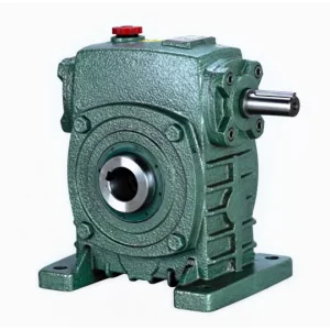
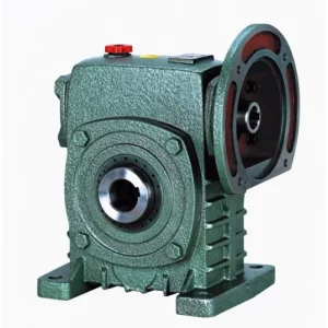
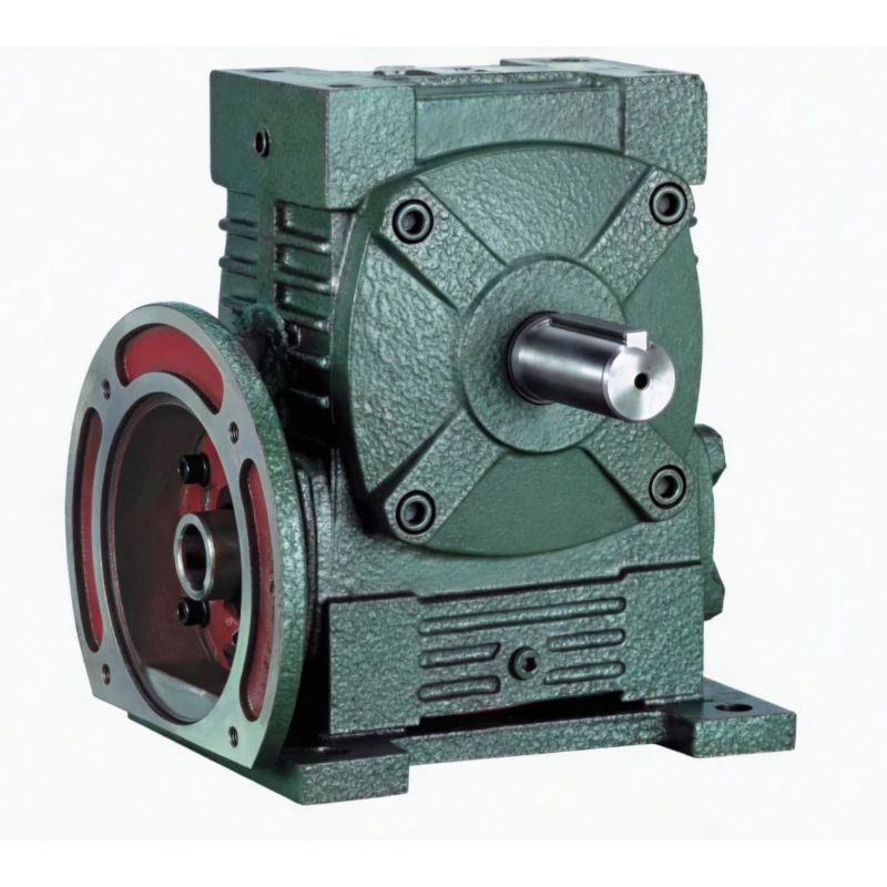
Product Structure — IEC Flange Input + Extended Multi-Direction Output
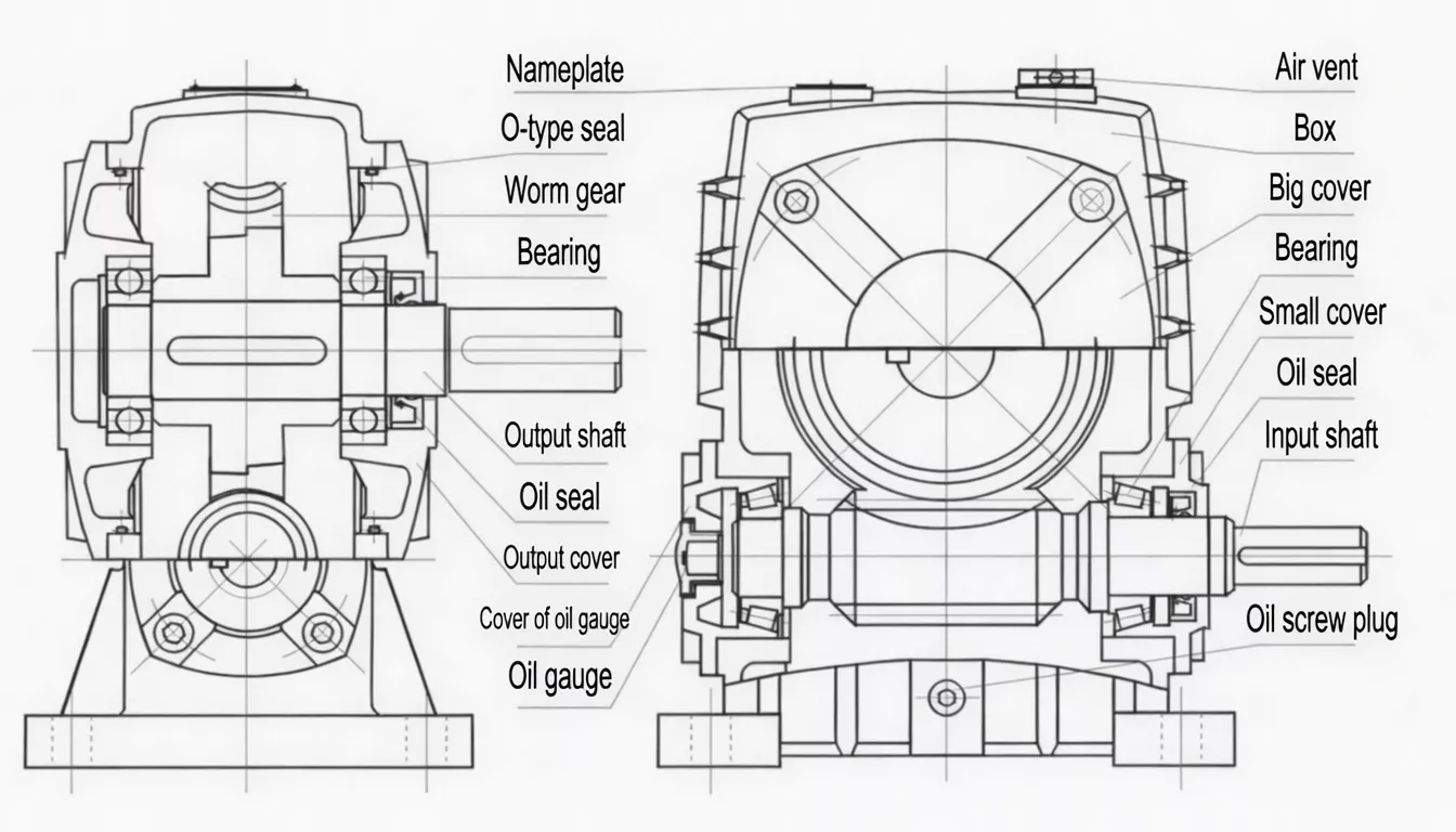
The WPWDA integrates the WPWD motor flange at the input with the WPWA extended housing body at the output. The IEC pilot register accepts the motor shaft directly at one end; the extended housing provides structural support for the output shaft in multiple direction configurations, with M, N, E, F, G dimensions defining the extended body geometry that accommodates varied agitator and shaft connection angles.
| Motor Input | IEC 60034-7 flange + keyed bore — motor shaft direct, no coupling |
| Output | Extended shaft (LL); multi-direction positions; solid shaft with keyway |
| Base | Universal flanged base (AC, BC); multi-orientation mounting |
| Motor Range | 0.12 kW (size 40) to 15 kW (size 250) |
| Housing | FC25 cast iron; elongated body for output direction flexibility |
| Self-Locking | At ratios ≥1/30 in all mounting orientations |
✅ Key Features & Benefits
IEC Motor Direct + Multi-Direction Output — Two Features Together
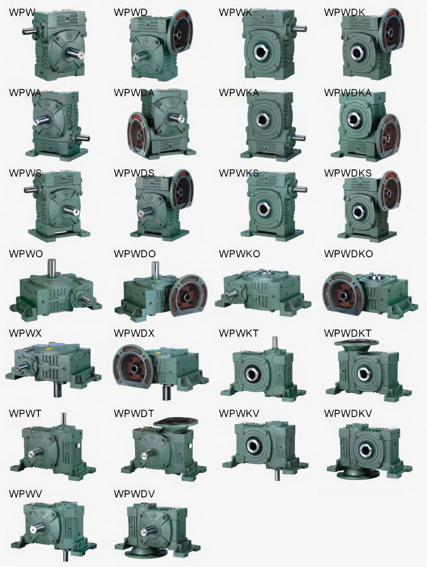
The WPWDA uniquely combines IEC motor direct-mount (no input coupling) with extended multi-direction output shaft geometry. No other single product in the WPW series provides both: WPWD has motor-direct but standard output; WPWA has multi-direction output but standard input shaft. WPWDA delivers both simultaneously. Keywords: motor-direct multi-direction universal worm reducer, IEC flange extended output worm gearbox.
Extended Output Shaft for Long-Reach Agitator Connections
The extended LL housing body and E, F, G output geometry provide the clearance needed to connect to vessel agitator shafts, tall-mounted agricultural auger heads, and elevated machine drive shafts where the gearbox must sit above or beside the driven shaft connection point.
Universal Flanged Base — Mount at Any Angle
The WPW universal flanged base allows the WPWDA to be mounted in any of the supported orientations with correct oil lubrication in each position. Multi-face oil ports confirm correct gear immersion whether the unit is horizontal, inclined, or vertical.
Rapid Motor Swap in Multi-Orientation Installations
The IEC pilot register allows motor replacement in under 15 minutes regardless of mounting orientation — a particular advantage for food processing and pharmaceutical multi-angle machine drives where motor downtime must be minimised without disassembling the machine structure.
Wide Motor Range — 0.12 to 15 kW
Twelve size groups accepting 0.12 kW to 15 kW motors provide the complete range of chemical vessel, agricultural equipment, and general industry motor-direct multi-direction drive requirements from small laboratory agitators to large industrial vessel drives.
Self-Locking for Safe Load Holding in Any Position
At ratios ≥1/30, the WPWDA self-locks in any supported mounting orientation — providing passive load holding for agitators, augers, and elevated equipment when the motor is de-energised, regardless of the output shaft direction.
Industry Applications
The WPWDA is specified where motor-direct input convenience must be combined with extended multi-direction output flexibility:
Chemical Vessel AgitatorsTop-entry and side-entry chemical vessel agitator drives where the WPWDA provides IEC direct motor mounting AND the extended output shaft direction needed to connect to the agitator shaft at the required angle without adapter boxes.
Agricultural MachineryAgricultural auger elevator drives, seed conveyor head drives, and grain handling equipment with varied motor-to-shaft angles where IEC motor-direct convenience is required alongside output direction flexibility.
Brewery & Food VesselsFermentation vessel agitator drives, food mixing vessel drives, and brewery conditioning tank drives requiring motor-direct convenience and flexible output positioning above the vessel structure.
Inclined Machine DrivesInclined conveyor drives, tiered production line equipment drives, and non-horizontal machine structures where the WPWDA’s motor-direct input simplifies motor maintenance while the multi-direction output accommodates the inclined geometry.
Pharmaceutical EquipmentGMP-compliant pharmaceutical vessel agitator and blending equipment drives requiring IEC motor-direct operation (for clean, coupling-free motor maintenance) and output shaft direction flexibility.
General OEM MachineryMachine builders who need a single motor-direct product specification covering both standard and non-standard output shaft directions across a range of machine variants — eliminating the need for separate WPWD and WPWA product specifications.
Quality Control & Certification
ISO 9001:2015 & CE
Full ISO 9001:2015 QMS. CE Declaration of Conformity. IEC flange CMM verified (≤0.05 mm TIR). Multi-orientation oil fill documentation for all rated positions supplied with each unit. Food/pharma GMP documentation packages available on request.
Flange + Output Shaft Verification
Each WPWDA undergoes: (1) IEC flange concentricity CMM check (≤0.05 mm TIR); (2) extended output shaft tip run-out check (≤0.05 mm TIR) — verifying geometric accuracy at the driven equipment connection point; (3) 45-min run test confirming noise ≤72 dB(A), seal integrity, and torque ±5% of rated.
Material Standards
Housing: FC25 cast iron (≥250 MPa). Worm: 20CrMnTi (≥58 HRC). Wheel: ZCuSn10Pb1 tin-bronze. Food-grade lubricant factory-fill (NSF H1) on request for food and pharmaceutical applications.
Why Choose Ever-power for WPWDA Gearboxes
We supply WPWDA motor-direct multi-direction universal worm gearboxes to chemical equipment OEMs, agricultural machinery builders, and food processing equipment manufacturers in Germany, Mexico, Singapore, Australia, and over 60 countries. Our combined IEC flange CMM check and extended shaft tip run-out verification ensures WPWDA customers receive a unit with correct motor fit AND correct output shaft geometry at the point of driven equipment connection.
- ✅ IEC flange CMM + output shaft tip run-out — both verified every unit
- ✅ Motor compatibility service — confirm motor fit before production
- ✅ Custom shaft extensions for long-reach agitator applications
- ✅ Food-grade lubricant option for GMP applications
- ✅ 20+ years export record — Germany, Mexico, Singapore, Australia and beyond
⭐ Customer Reviews
“We use WPWDA on our chemical reactor vessel agitator drives where the output shaft must reach the agitator at a specific angle. The IEC flange motor mounting keeps installation clean and motor changes fast, and the extended output shaft geometry gives us the reach we need without any angle-drive adapter. Two features in one product — exactly what we needed.”
Nathan B., Process Engineer
Chemical Equipment OEM, Victoria, Australia
“We integrate WPWDA into our agricultural auger elevator drives where motor-direct convenience and output direction flexibility are both required. The IEC flange speeds motor installation on the farm, and the multi-direction output accommodates our varied elevator angles. Consistent quality from Ever-power across multiple machine variants.”
Tobias W., Machine Design Engineer
Agricultural Equipment Manufacturer, Bavaria, Germany
“WPWDA on our food mixing vessel drives at various installation angles. The motor-direct flange eliminates the coupling maintenance that was our main service call-out on our previous machines, and the multi-direction output fits our vessel layout exactly. The food-grade lubricant option is used on all our food-contact applications.”
Rafael O., Applications Engineer
Food Processing Equipment, Guadalajara, Mexico
“We use WPWDA for our pharmaceutical mixer vessel drives. The IEC flange is clean for GMP environments and the multi-direction output accommodates our vessel mounting arrangements. Good quality, consistent IEC flange dimensions. GMP documentation pack was useful for our qualification records.”
Dennis C., Equipment Engineer
Pharmaceutical Equipment, Singapore
❓ Frequently Asked Questions
What is the difference between WPWDA and WPWD?
The WPWD has an IEC motor flange and standard (non-extended) output shaft — identical to the WPW platform. The WPWDA has the same IEC motor flange but with an extended output shaft and housing body (LL, M, N, E, F, G dimensions) that supports multi-direction output shaft positions — the same extended geometry as the WPWA. Choose WPWD for standard output shaft applications; choose WPWDA when the output shaft must reach the driven equipment at a non-standard angle or longer distance.
Can I specify a custom output shaft length for the WPWDA?
Yes — the standard LL dimension is specified in the table for each size. For applications requiring a longer output shaft extension (e.g. deep-vessel agitators), custom LL extensions are available for OEM orders. Contact us with your required output shaft projection length and we will confirm availability and any tooling requirements.
Is the WPWDA available with food-grade lubricant?
Yes — on request, we factory-fill WPWDA units with NSF H1 registered food-grade gear oil. Specify at order placement. This is widely used for WPWDA units in food mixing vessel, brewery agitator, and pharmaceutical vessel agitator applications where food-safe machinery documentation is required.
What output shaft directions does the WPWDA support?
The WPWDA supports the same shaft-direction positions as the WPWA — providing multiple positions including horizontal, vertical, and intermediate angles. Contact us with your specific required output shaft direction and we will confirm the correct position and oil fill configuration for your installation layout.
What is the maximum output torque of the WPWDA?
At 1500 r/min input, size 250 with a 15 kW motor at ratio 1/60 delivers approximately 3,025 Nm (from the WPD.WPDK.WPWD.WPWDK power and torque table). Contact our engineers with your required motor power and ratio for a precise calculation.
Motor-Direct + Multi-Direction Output — Get WPWDA Quote
When you need IEC motor-direct convenience AND multi-direction output flexibility in one unit, the WPWDA is the solution. Our engineers will verify motor compatibility and confirm the correct output shaft configuration for your application.