Beschreibung
WPWEDK Flange-Mounted Universal Hollow Shaft Double Speed Worm Gear Reducer — Zero Couplings at Both Ends with 1/200–1/900 Ultra-High Ratio on Universal Mounting Platform
Precision slow drives — textiles, paper, packaging, and material handling systems requiring output speeds below 10 r/min from a 1500 r/min motor — face a compound challenge: a two-stage reducer is needed for the high ratio, yet the application also benefits from zero coupling hardware at both the motor and driven shaft interfaces. The WPWEDK flange-mounted universal hollow shaft double speed worm gear reducer resolves this by integrating IEC motor flange, H7 hollow output bore, two-stage worm cascade (1/200–1/900), and WPW universal flanged base in one FC25 cast iron housing.
The result is the most compact zero-coupling ultra-high ratio drive available on the WPW universal platform: motor + WPWEDK + driven shaft, three components, zero couplings, ratios from 1/200 to 1/900. Motors 0.12–5.5 kW, bore 30–110 mm, 9 size groups. Über Ever-power | Request a Ratio Selection Guide
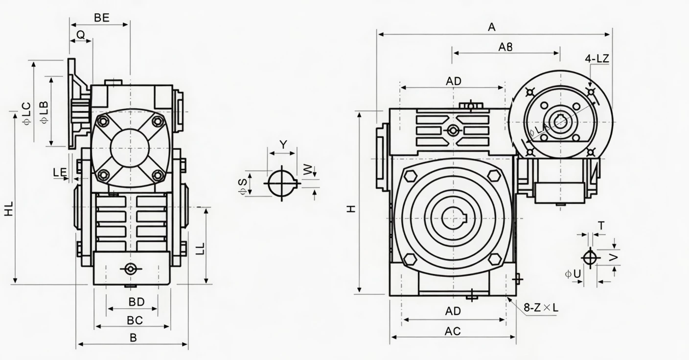
Technical Specifications
Motor flange: LA/LB/LC/LE/LZ per IEC 60034-7. Input hole: Q, U, T×V. Base: AC, BC, AD, BD, Z×L. Hollow bore: S (H7); W×Y = keyway. LL = two-stage housing length; H = overall height. Reference input speed 1500 r/min. All dimensions in mm.
| Size | Power(kW) | Ratio | A | AB | B | BE | AC | BC | AD | BD | LL | H | Z×L | LA | LB | LC | LE | LZ | Q | U | T×V | S(bore) | W×Y | Wt(kg) |
|---|---|---|---|---|---|---|---|---|---|---|---|---|---|---|---|---|---|---|---|---|---|---|---|---|
| 40-70 | 0.12 | 1/200–1/900 | 314 | 153 | 130 | 75 | 152 | 86 | 125 | 65 | 200 | 215 | M10×25 | 115 | 95 | 140 | 4 | M8 | 31 | 11 | 4×12.8 | 30 | 8×33.3 | 18 |
| 50-80 | 0.18 | 314 | 144 | 150 | 83 | 169 | 102 | 140 | 70 | 235 | 250 | M12×28 | 115 | 95 | 140 | 4 | M8 | 31 | 11 | 4×12.8 | 35 | 10×38.3 | 28 | |
| 60-100 | 0.37 | 1/200 | 387 | 175 | 160 | 91 | 216 | 117 | 180 | 90 | 290 | 310 | M12×30 | 130 | 110 | 160 | 4 | M8 | 33 | 14 | 5×16.3 | 40 | 12×43.3 | 44 |
| 70-120 | 0.37/0.75 | 1/300–1/400 | 425/445 | 193 | 175 | 109/111 | 256 | 124 | 220 | 100 | 345/350 | 370 | M14×32 | 130/165 | 110/130 | 160/200 | 4 | M8/M10 | 40/42 | 14/19 | 5×16.3/6×21.8 | 45 | 14×48.8 | 66 |
| 80-135 | 0.75/1.5 | 1/500–1/600 | 499 | 226 | 210 | 125 | 296 | 147 | 260 | 110 | 400 | 425 | M16×35 | 165 | 130 | 200 | 4.5 | M10 | 48/52 | 19/24 | 6×21.8/8×27.3 | 60 | 18×64.4 | 101 |
| 100-155 | 1.5 | 1/800 | 570 | 269 | 256 | 148 | 345 | 185 | 280 | 120 | 458 | 461 | M16×35 | 165 | 130 | 200 | 4.5 | M10 | 52 | 24 | 8×27.3 | 70 | 20×74.9 | 139 |
| 120-175 | 2.2/3.0 | 1/900 | 631 | 287 | 282 | 181 | 374 | 192 | 320 | 140 | 518 | 521 | M16×35 | 215 | 180 | 250 | 5 | M12 | 63 | 28 | 8×31.3 | 80 | 22×85.4 | 196 |
| 135-200 | 3.0/4.0 | 680 | 318 | 320 | 202 | 412 | 230 | 360 | 150 | 580 | 575 | M20×36 | 215 | 180 | 250 | 5 | M12 | 63 | 28 | 8×31.3 | 85 | 22×90.4 | 285 | |
| 155-250 | 5.5 | 815 | 380 | 400 | 247 | 500 | 285 | 420 | 190 | 705 | 700 | M24×42 | 265 | 230 | 300 | 5 | M12 | 83 | 38 | 10×41.3 | 110 | 28×116.4 | 450 |
* LL = two-stage housing total length. AC, BC = flanged base arm width/depth; AD, BD = anchor bolt hole positions. S = hollow bore H7; W×Y = keyway. Z×L = anchor bolt specification. LA, LB, LC per IEC 60034-7. Motor power per size group shown — match to correct IEC flange dimensions.
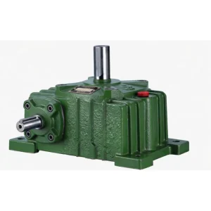
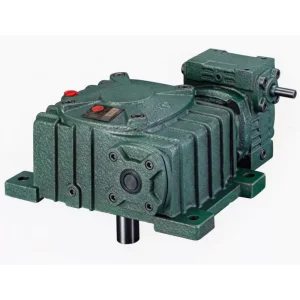
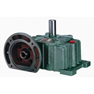
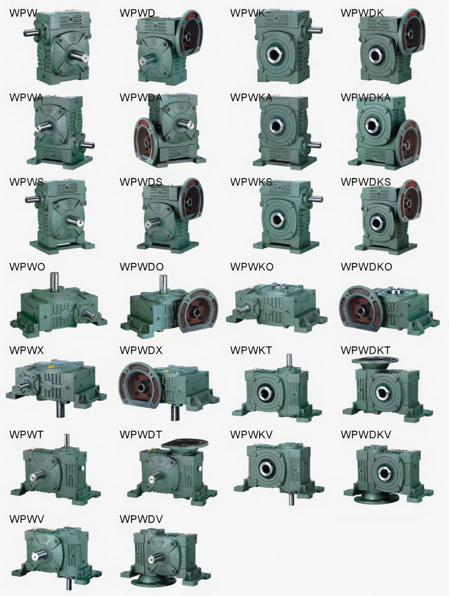
Product Structure — IEC Flange + Two-Stage Worm Cascade + Hollow Bore + Universal Base
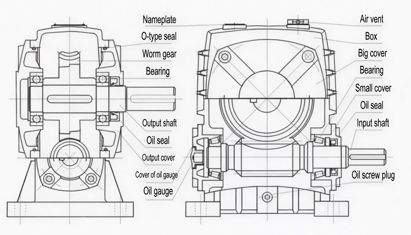
The WPWEDK elongated housing accommodates two worm-and-wheel stages in series, with the IEC motor flange at one end and the H7 hollow bore at the other. The WPW universal flanged base (AC, BC, AD, BD, Z×L) is integrated into the same casting, providing multi-orientation mounting with correct oil lubrication across all rated positions via multi-face oil ports.
| Motor Input | IEC 60034-7 flange + keyed bore — direct, no coupling |
| Drive | Two worm-and-wheel stages in series — ratio 1/200 to 1/900 |
| Output | H7 hollow bore + keyway; 30–110 mm — driven shaft direct, no coupling |
| Base | Universal flanged base; multi-orientation; 4 anchor bolt positions |
| Result | Motor + WPWEDK + shaft = 3 components, 0 couplings, ratio up to 1/900 |
| Self-Locking | Strong static self-locking at all ratios ≥1/400 |
✅ Key Features & Benefits
Zero Couplings at Both Ends — with 1/200–1/900 Ultra-High Ratio
No single-stage product can achieve these ratios. No other WPWE double-speed product simultaneously provides IEC motor direct AND hollow bore output AND universal base. The WPWEDK delivers three zero-coupling features (IEC flange + hollow bore + universal multi-orientation base) AND the two-stage cascade in one housing. Keywords: IEC flange hollow shaft double speed worm reducer, zero-coupling ultra-high ratio worm gearbox.
Universal Flanged Base — Any Orientation at 1/200–1/900
The WPW universal flanged base allows the WPWEDK to be mounted at any supported orientation even at extreme 1/900 output speeds — where reaction torques from the two-stage output are at their maximum and the flanged base rigidity is most valuable for preventing bolt loosening in sustained service.
IEC Motor Swap at Ultra-High Ratio Drives
At 1/900 ratio and 1500 r/min input, output speed is just 1.67 r/min. Maintenance access to the motor is critical in slow precision drives. The IEC flange enables motor replacement without disturbing the hollow bore shaft connection — maintaining the driven equipment position precisely during the motor swap.
Ultra-Strong Self-Locking at High Ratios
At combined ratios ≥1/400, the two-stage WPWEDK provides extremely strong static self-locking — securing connected loads against gravity reversal, residual tension forces, or process pressure when the motor is de-energised. The hollow bore ensures the driven shaft is rigidly held while self-locking acts.
Precision Slow Drives for Textile & Paper
At 1500 r/min input and ratio 1/900, output is 1.67 r/min — enabling very precise slow rotation control for textile winding, paper web tension, and inspection machinery where gear-to-gear ratio stability (not just motor speed control) is the primary precision mechanism.
9 Size Groups — Full Power Range
Nine size groups accepting 0.12 kW to 5.5 kW motors cover the complete range of ultra-high ratio hollow shaft zero-coupling drive requirements from small textile machine spools to large conveyor slow positioning drives.
Industry Applications
WPWEDK is specified for precision slow drives requiring zero-coupling IEC motor-direct input and coupling-free hollow bore output at 1/200–1/900 ratios:
Textile Precision Slow DrivesTextile winding machine hollow shaft motor-direct slow drives, industrial loom auxiliary precision positioning drives, and yarn tension control system very slow drives requiring 1/400–1/900 ratios with zero coupling hardware.
Paper & Converting MachineryPaper web tension roller hollow shaft motor-direct drives, converting machine precision slow positioning drives, and large format printing machinery auxiliary slow speed drives.
Packaging Precision DrivesPrecision slow indexing conveyor hollow shaft motor-direct drives, packaging machine index positioning drives, and label application system slow precision drives requiring coupling-free motor-direct ultra-high ratio.
Material Handling Slow DrivesWarehouse heavy-duty slow conveyor positioning drives, production line precision indexing drives, and material handling system slow precision transfer drives requiring 1/400+ ratio at zero coupling.
Machine Tool AuxiliariesCNC machining centre precision slow table positioning drives, industrial press feeding mechanism precision drives, and production line slow indexing system hollow shaft motor-direct drives.
Infrastructure Slow MechanismsLock gate and sluice valve slow operating mechanism hollow shaft motor-direct drives, bridge machinery auxiliary slow drives, and dam gate control mechanism drives requiring 1/600–1/900 ratio.
Quality Control & Certification
ISO 9001:2015 & CE
Full ISO 9001:2015 QMS. CE Declaration of Conformity. IEC flange CMM + bore H7 + base flatness all verified. Textile and paper industry OEM documentation available. Two-stage run test including ultra-low speed output verification.
Dual Interface + Two-Stage Run Test
Each WPWEDK: (1) IEC flange CMM (≤0.05 mm TIR); (2) bore H7 plug gauge + concentricity CMM; (3) base flatness CMM (≤0.05 mm TIR); (4) 45-min two-stage run test — noise ≤75 dB(A), both stage seals, output torque ±5% of rated. Three CMM checks + two-stage run test.
Two-Stage Material Standards
Housing: FC25 cast iron. Both worm shafts: 20CrMnTi (≥58 HRC). Both wheel rims: ZCuSn10Pb1 tin-bronze. Material certs and SGS/BV inspection on request for textile, paper, and infrastructure sector procurement.
Why Choose Ever-power for WPWEDK Gearboxes
We supply WPWEDK zero-coupling ultra-high ratio universal worm gearboxes to textile machinery OEMs, paper machine equipment builders, and precision machine manufacturers in Germany, Japan, Italy, Australia, and over 60 countries. Our three CMM checks plus two-stage run test — the most comprehensive inspection for any double-speed product in the WPW series — ensures every WPWEDK delivers precise ratio, correct interface dimensions, and stable two-stage performance.
- ✅ Three CMM checks + two-stage run test — every unit
- ✅ OEM batch consistency for textile/paper applications
- ✅ Motor compatibility confirmation service before production
- ✅ Custom bore diameters for precision machine shaft sizes
- ✅ 20+ years export record — Germany, Japan, Italy, Australia and beyond
⭐ Customer Reviews
“We use WPWEDK at 1/600 ratio on our industrial winding machine hollow shaft motor-direct drives. The IEC flange motor-direct and hollow bore shaft engagement eliminate both couplings, and the 1/600 ratio gives us the very slow winding speed we need from our standard motors. The two-stage gear precision provides extremely stable ratio — important for consistent winding tension. Excellent product.”
Mark J., Machine Design Engineer
Textile Machinery OEM, Victoria, Australia
“WPWEDK on our paper web tension roller hollow shaft motor-direct slow drives. At 1/800 ratio, the output is stable and consistent — essential for our tension control system. The IEC flange enables motor changes without disturbing the roller shaft engagement. The three CMM checks and two-stage run test report satisfy our quality documentation requirements.”
Klaus F., Drive Engineer
Paper Machine OEM, Hamburg, Germany
“We integrate WPWEDK into our precision indexing conveyor hollow shaft motor-direct drives. At 1/900 ratio, we achieve the very slow precise indexing speed our assembly line requires. Zero coupling hardware at both ends simplifies our machine design significantly. Good quality from Ever-power, consistent across multiple production batches.”
Kenji T., Applications Engineer
Precision Machinery Manufacturer, Osaka, Japan
“WPWEDK for our packaging machine precision slow indexing hollow shaft motor-direct drives. The ultra-high ratio combined with zero coupling IEC input and hollow bore output is exactly our specification. Good quality, three CMM check report is a useful quality document. Delivery to Italy is reliable. Would recommend.”
Matteo R., Technical Manager
Packaging Equipment OEM, Bologna, Italy
❓ Frequently Asked Questions
What is the difference between WPWEDK and WPWDK?
The WPWDK is a single-stage drive with ratios 1/5–1/60. The WPWEDK uses two worm-and-wheel stages in series, achieving ratios 1/200–1/900 — impossible with a single stage. Both have IEC motor flange + hollow bore + universal flanged base. Choose WPWDK when 1/5–1/60 ratios are sufficient; choose WPWEDK when ultra-high 1/200–1/900 ratios are required for very slow precision drives.
What output speed does the WPWEDK deliver at 1500 r/min input?
At 1500 r/min input: ratio 1/200 → 7.5 r/min output; ratio 1/400 → 3.75 r/min; ratio 1/600 → 2.5 r/min; ratio 1/900 → 1.67 r/min. These ultra-low output speeds are what makes the WPWEDK essential for textile winding, paper tension, and precision indexing drives where the gear ratio itself provides the speed precision, not just the motor control.
Is there any efficiency loss in the WPWEDK two-stage versus a single stage?
Yes — two worm meshes means two sets of mesh losses. Overall efficiency at 1/600 ratio is typically 45–65%, compared to 65–80% for a single-stage 1/60 ratio unit. This is acceptable for the slow precision applications where WPWEDK is used, where output torque is high (from the two-stage multiplication) and the moderate efficiency is balanced by the precision ratio stability.
What lubricant is recommended for the WPWEDK two-stage housing?
With two heat-generating worm gear stages in an enclosed housing, thermal management is more important than for single-stage units. We recommend synthetic PG ISO VG 460 oil, which has lower friction coefficient than mineral oil (improving efficiency slightly), better thermal stability, and longer drain intervals. First change at 500 hours; subsequent changes every 3,000 hours.
Can the WPWEDK hollow bore be used for direct conveyor drum shaft mounting?
Yes — at ratios 1/200–1/400, the WPWEDK can be used for slow conveyor positioning drives. The hollow bore engages the drum shaft directly. For continuous conveyor drives, ensure the selected ratio delivers sufficient output torque for your load — use the WPED.WPEDK.WPWED.WPWEDK power and torque table (PDF page 32) for your specific motor power and ratio.
Zero Couplings + Ultra-High Ratio — Get WPWEDK Quote Today
For precision slow drives requiring zero-coupling motor-to-shaft simplicity at 1/200–1/900 ratios on a universal mounting platform, the WPWEDK is the definitive solution. Our engineers will verify ratio, bore size, and motor compatibility at no charge.